- Introduction
- The Basics of a Sine Wave
- Key Characteristics
- Visualizing the Sine Wave
- Applications of Sine Waves in Electrical Engineering
- Signal Processing
- AC Power Generation
- Communication Systems
- Using Oscilloscopes to Measure Sine Waves
- Connect the Probe
- Adjust the Settings
- Analyze the Waveform
- Additional Tips for Accurate Measurements
- Common Issues and Solutions
- Distorted Waveforms
- Unstable Display
- Incorrect Measurements
- Additional Tips
- Conclusion
- Whenever You’re Ready, Here Are 5 Ways We Can Help You
Did you know that sine waves are the purest form of oscillation found in nature? They’re not just simple waveforms; they form the foundation of many technologies you encounter every day. From the power in your home to the signals transmitting your data.
Let's explore what makes this waveform so indispensable and how it directly impacts your work.
The Basics of a Sine Wave
A sine wave is a smooth, periodic oscillation that represents a fundamental form of a waveform. Mathematically, it's represented as:
y(t) = A sin(2πft + φ)
where:
- y(t) = instantaneous value of the waveform at time t
- A = amplitude
- f = frequency (number of cycles per second, measured in Hertz)
- φ = phase shift (offset of the wave from a reference point in degrees or radians)
Key Characteristics
- Amplitude (A): The maximum value of the wave, indicating the peak level of the signal.
- Frequency (f): The number of cycles the wave completes in one second. Higher frequencies mean more cycles per second. The period T is defined as the time it takes to complete one cycle and is derived from the inverse of the frequency (T=1/f)
- Phase (φ): Describes the wave's shift from a reference point. A phase shift can lead to constructive or destructive interference between two overlapping waves.
| Key Takeaway |
|---|
| Sine waves are the foundational building blocks in electrical engineering, important for analyzing and designing systems in signal processing, power generation, and communications. Understanding and accurately measuring sine waves is essential for designing and optimizing efficient and reliable systems. |
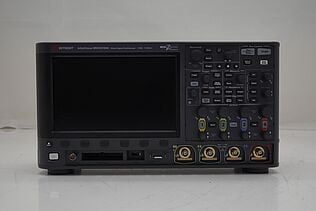
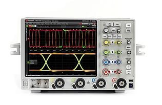
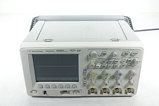
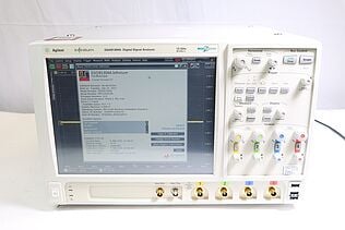
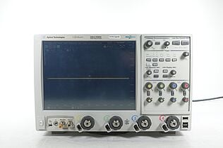
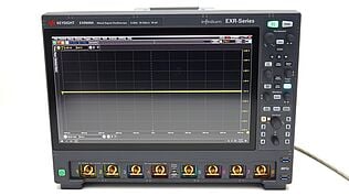
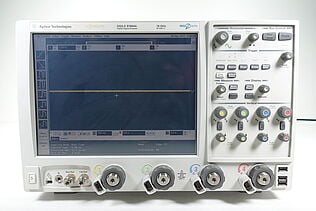
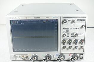
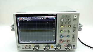
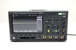
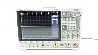
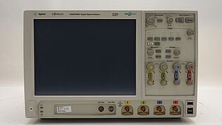
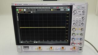
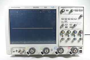
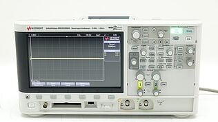
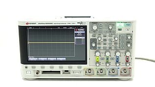
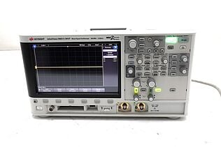
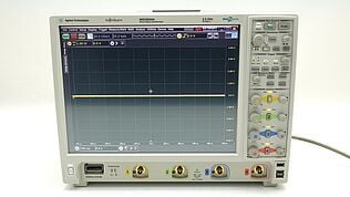
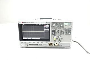
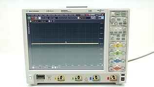
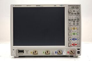
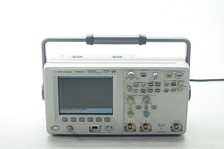
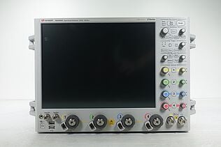
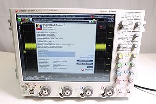
Discover Our Selection of Used Oscilloscopes
Visualizing the Sine Wave
Consider the following table to visualize how the sine wave's parameters affect its shape:
| Parameter | Effect on Sine Wave |
|---|---|
| Amplitude | Changes the height of the peaks |
| Frequency | Changes the number of cycles per second and how close the peaks appear together |
| Phase | Shifts the wave horizontally |
| Period | Changes the duration of one complete cycle |
This table highlights how each parameter influences the sine wave, allowing you to understand its behavior and make necessary adjustments in your applications.
Applications of Sine Waves in Electrical Engineering
Sine waves play a critical role in various applications within electrical engineering. Their unique properties make them ideal for many functions, from signal processing to power generation and communication systems.
Signal Processing
Sine waves are fundamental in signal processing. They serve as building blocks for more complex signals. When analyzing signals, you often separate them into individual sine waves using Fourier Transform. This allows you to understand and manipulate signal components effectively.
AC Power Generation
In AC power systems, the voltage and current waveforms are typically sinusoidal. This shape ensures efficient energy transmission and minimal harmonic distortion. You rely on sine waves to design and analyze power systems, ensuring they operate safely and efficiently.
Communication Systems
Sine waves are integral to communication systems. Modulating sine waves allows you to transmit information over various mediums. Understanding how to manipulate sine waves helps you optimize data transmission and minimize interference.
Using Oscilloscopes to Measure Sine Waves
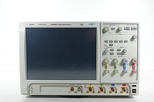
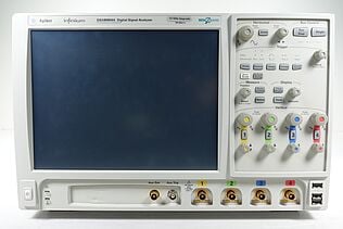
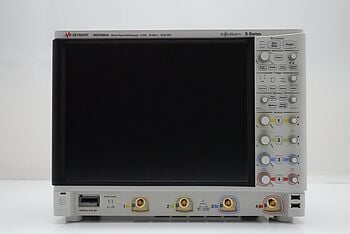
When you measure sine waves, oscilloscopes become your go-to tools. Here's a detailed guide to help you effectively measure and analyze sine waves using an oscilloscope.
Connect the Probe
- Attach the probe: Securely connect the oscilloscope probe to the point in the circuit where you want to measure the sine wave. Ensure the probe is properly grounded to avoid noise and interference.
- Compensate the probe: Before taking measurements, compensate the probe to ensure accurate readings. Connect the probe to the oscilloscope's calibration signal and adjust the compensation trimmer until the displayed square wave is flat-topped without overshoot or ringing.
Adjust the Settings
- Time base: Set the oscilloscope's time base (horizontal scale) to display a few cycles of the sine wave clearly. Adjust the time base to zoom in or out on the waveform as needed.
- Voltage scale: Adjust the voltage scale (vertical scale) to fit the sine wave within the oscilloscope's display. Ensure the peaks of the sine wave are clearly visible without clipping.
- Triggering: Set the trigger level to stabilize the waveform display. Adjust the trigger mode (edge, pulse, or level) to capture the sine wave consistently. For most sine wave measurements, edge triggering works best.
Analyze the Waveform
- Amplitude measurement: Measure the peak-to-peak voltage (Vpp) to determine the amplitude of the sine wave. Use the oscilloscope's cursors or automated measurement functions to obtain precise readings.
- Frequency measurement: Calculate the frequency by measuring the time interval (period) between successive peaks of the sine wave. Most oscilloscopes have a built-in frequency measurement function that simplifies this process.
- Phase measurement: To measure the phase difference between two sine waves, connect two probes to the respective points in the circuit. Use the oscilloscope's dual-channel mode to display both waveforms simultaneously. Measure the horizontal distance between corresponding points (e.g., peaks) of the two waves and calculate the phase shift in degrees or radians.
Additional Tips for Accurate Measurements
- Bandwidth: Ensure the oscilloscope's bandwidth is sufficient to capture the frequency of the sine wave accurately. A bandwidth of at least five times the sine wave frequency is recommended for precise measurements.
- Sampling rate: Use a high sampling rate to capture detailed information about the sine wave. A rate of at least ten times the highest frequency component of the sine wave ensures accurate representation.
- Noise reduction: Minimize electrical noise by using proper grounding techniques and shielding. Keep probe leads as short as possible and avoid running them parallel to noisy power lines or switching circuits.
- Calibration: Regularly calibrate your oscilloscope to maintain measurement accuracy. Follow the manufacturer's guidelines for calibration procedures and intervals.
By following these steps, you can accurately measure and analyze sine waves using an oscilloscope, gaining valuable insights into your circuit's performance and behavior.
Common Issues and Solutions
When using oscilloscopes to measure sine waves, you might encounter several common issues. Here’s a more detailed look at these issues and how to address them.
Distorted Waveforms
Causes:
- Improper grounding: Poor grounding can introduce noise and interference, distorting the waveform.
- Probe calibration: If the oscilloscope probe is not properly compensated, it can distort the signal.
- Bandwidth limitations: Using an oscilloscope with insufficient bandwidth can fail to capture the waveform accurately.
Solutions:
- Proper grounding: Ensure that the probe's ground lead is securely connected to a good ground point in the circuit. Minimize the ground lead length to reduce noise pickup.
- Calibrate the probe: Connect the probe to the oscilloscope’s calibration output and adjust the compensation trimmer until the displayed calibration signal is a clean square wave.
- Choose the right oscilloscope: Select an oscilloscope with a bandwidth at least five times higher than the highest frequency component of the sine wave you are measuring.
Unstable Display
Causes:
- Incorrect triggering: If the oscilloscope's trigger settings are not properly configured, the waveform display can become unstable.
- Noise and interference: External noise can cause the display to jitter or become unstable.
Solutions:
- Set correct triggering: Adjust the trigger level so that it captures the waveform consistently. Use edge triggering for sine waves and ensure the trigger source is correctly set to the channel you are measuring.
- Use noise reduction techniques: Use proper shielding and grounding techniques to minimize noise. Use the oscilloscope’s noise filter functions if available.
Incorrect Measurements
Causes:
- Probe attenuation settings: Using the wrong attenuation setting on the probe can lead to inaccurate measurements.
- Oscilloscope calibration: An uncalibrated oscilloscope can provide incorrect readings.
Solutions:
- Verify probe attenuation: Ensure the probe’s attenuation setting (e.g., 1x, 10x) matches the oscilloscope’s input setting. If the probe is set to 10x, the oscilloscope should also be set to 10x.
- Regular calibration: Calibrate the oscilloscope regularly according to the manufacturer’s instructions. This ensures that all measurement functions are accurate.
- Check signal path: Inspect the signal path for any loose connections or damaged cables that could affect the measurement accuracy.
Additional Tips
- Use high-quality probes: Invest in high-quality probes that match the specifications of your oscilloscope.
- Monitor environmental conditions: Temperature and humidity can affect the performance of your oscilloscope. Keep the environment stable to maintain measurement accuracy.
- Understand your equipment: Familiarize yourself with the specific features and functions of your oscilloscope. Knowing how to use these features can help you troubleshoot issues more effectively.
By addressing these common issues and implementing the recommended solutions, you can ensure more accurate and reliable measurements when using oscilloscopes to analyze sine waves.
Explore Keysight’s Range of Oscilloscopes Today
Select up to 3 instruments to compare
Enable Notifications
In order to use this feature, you need to enable notifications.
Manage notification preferences
Conclusion
Sine waves are fundamental to electrical engineering, playing a crucial role in signal processing, AC power generation, and communication systems.
Understanding their characteristics—amplitude, frequency, phase, and period—allows you to design, analyze, and optimize various electrical systems effectively.
When you master the use of your oscilloscope and address common measurement issues, the result will be precise and reliable waveform analyses.
For high-quality measurement tools, visit the Keysight Used Equipment Store. Explore our premium selection of used oscilloscopes, spectrum analyzers, function generators, and multimeters. Elevate your work with reliable and affordable equipment.
Whenever You’re Ready, Here Are 5 Ways We Can Help You
- Browse our Premium Used Oscilloscopes.
- Call tech support US: +1 800 829-4444
Press #, then 2. Hours: 7 am – 5 pm MT, Mon– Fri - Talk to our sales support team by clicking the icon (bottom right corner) on every offer page
- Create an account to get price alerts and access to exclusive waitlists.
- Talk to your account manager about your specific needs.

