- Introduction
- How to Use the Voltage Divider Calculator
- What is a Voltage Divider?
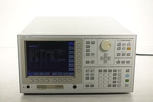
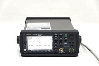
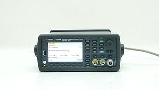
- Unlock Precision from the Start – Explore Our Used Voltage Testing Tools
- Voltage Divider Circuit
- Voltage Divider Formula
- Voltage Divider Rule
- Voltage Divider Applications
- Potentiometers
- Reading Resistive Sensors
- Level Shifting
- High Voltage Measurement
- Essential Tools for Working with Voltage Dividers
- Practical Tips and Troubleshooting
- Optimize Your Circuit Design with Precision Tools
- Whenever You’re Ready, Here Are 5 Ways We Can Help You
Ω
Ω
V
Do you find yourself frustrated by calculations, wishing there was a quicker way to optimize your circuit designs? You're not alone. Many engineers and technicians face the same obstacles when working on projects, where even small calculation errors can lead to big headaches.
What if there was a tool that could handle the math for you, allowing you to focus on what really matters — fine-tuning your design for maximum efficiency.
That's where our Voltage Divider Calculator comes in. It's a simple, intuitive tool designed to help you quickly determine the voltage drop across resistors, streamlining your workflow and giving you more time to innovate.
Whether you're designing a new circuit or troubleshooting an existing one, this calculator provides an easy way to achieve accurate results, helping you save time and reduce errors.
How to Use the Voltage Divider Calculator
The Voltage Divider Calculator helps you quickly find the output voltage or other unknowns in a circuit using two resistors in series. Here's how you can use this tool to streamline your calculations:
- Input Your Known Values:
- Voltage Source (Vs): Enter the total voltage supplied to your circuit.
- Resistance 1 (R1): Enter the resistance value of the first resistor.
- Resistance 2 (R2): Enter the resistance value of the second resistor.
- Output Voltage (Vout): Enter the desired or measured output voltage across the second resistor.
- Select Three Known Values:
- You need to input any three of the four values (Vs, R1, R2, Vout). The calculator will compute the missing value.
- Calculate:
- Click the “Calculate” button. The calculator will use the voltage divider formula to determine the unknown value and display it in the respective field. The formula used is: Vout = (Vs * R2) / (R1 + R2).
- For different inputs, the calculator will adjust and compute accordingly to provide the missing value.
- Reset Fields:
- If you want to perform a new calculation, click the “Reset” button to clear all fields.
By following these steps, you can easily find the required value to optimize your circuit design without manual calculations, ensuring accuracy and efficiency in your projects.
What is a Voltage Divider?
A voltage divider is a simple circuit that divides the input voltage into smaller parts. It typically consists of two resistors connected in series.
- Resistor 1 (R1): The first resistor in the series.
- Resistor 2 (R2): The second resistor in the series where you measure the output voltage.
- Output Voltage: The voltage across R2, derived from the ratio of the two resistors.

Voltage dividers are essential for adjusting voltage levels within circuits, whether for powering components at lower voltages or interfacing different parts of a circuit. They play a critical role in both simple and complex electronic designs.
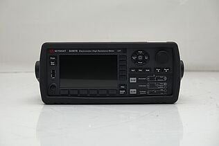
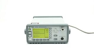
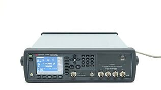
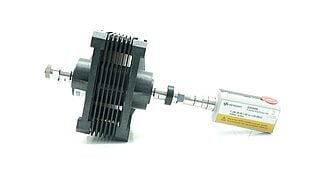
Unlock Precision from the Start – Explore Our Used Voltage Testing Tools
Voltage Divider Circuit
A standard voltage divider circuit consists of two resistors, R1 and R2, connected in series with an input voltage source, Vs. The input voltage is applied across the series combination of these two resistors. The voltage drop is distributed across each resistor according to their resistance values. The output voltage (Vout) is taken from the junction between R1 and R2, representing a fraction of the input voltage.
| Input Voltage (Vs) | Resistance 1 (R1) | Resistance 2 (R2) | Output Voltage (Vout) |
| 10V | 1kΩ | 2kΩ | 6.67V |
| 10V | 2kΩ | 1kΩ | 3.33V |
| 5V | 1kΩ | 1kΩ | 2.5V |
Example Calculation: If you have an input voltage of 10V, with R1 = 1kΩ and R2 = 2kΩ, the output voltage (Vout) is calculated as Vout = (Vs * R2) / (R1 + R2) = (10 * 2000) / (1000 + 2000) = 6.67V.
Voltage Divider Formula
The voltage divider formula calculates the output voltage in a circuit with two resistors connected in series. The formula is:
Vout = (Vs * R2) / (R1 + R2)
- Vs: Input voltage supplied to the circuit.
- R1: Resistance of the first resistor.
- R2: Resistance of the second resistor.
- Vout: Output voltage across the second resistor.
Derivation: Using Ohm's Law (V = IR), the current (I) in the circuit is I = Vs / (R1 + R2). The voltage across R2 (Vout) is then I * R2, leading to the formula Vout = (Vs * R2) / (R1 + R2).
Voltage Divider Rule
The voltage divider rule offers a straightforward method for calculating the voltage drop across each resistor in a series circuit. By applying the rule, you can determine the output voltage across any resistor without needing to solve complex circuit equations. For example, in a circuit with two resistors (R1 and R2) and an input voltage (Vs), the output voltage across R2 can be calculated using the formula Vout = (Vs * R2) / (R1 + R2).
This rule is particularly useful in circuits where you need to step down voltage levels, such as in sensor interfaces or biasing transistors.
Compared to methods like Kirchhoff's Voltage Law (KVL), the voltage divider rule provides a quick, less complex solution for series circuits. However, it has limitations; its accuracy decreases with non-ideal resistors or when the output is connected to a load, as these factors can alter the current and, consequently, the voltage drop across the resistors.
Voltage Divider Applications
Voltage dividers are essential in a variety of applications, from high-voltage measurement to level shifting, and engineers rely on them to perform accurately in every scenario.
When deadlines are tight, and there’s no room for error, having reliable, high-performance equipment is crucial. That’s why Keysight’s premium pre-owned equipment is the smart choice—delivering the quality and dependability you need, without the long wait times, so you can keep your projects moving forward with confidence.
Here are some of the key applications where voltage dividers prove invaluable:
Potentiometers
Potentiometers act as adjustable voltage dividers, enabling precise control of output voltage by varying resistance. They are commonly used in applications such as adjusting volume in audio equipment or fine-tuning circuits. For example, in a stereo system, a potentiometer can adjust the output volume by changing the voltage delivered to the amplifier, providing smooth control over sound levels.
Reading Resistive Sensors
Voltage dividers are essential for reading resistive sensors, like thermistors or photoresistors, by converting resistance changes into measurable voltage variations. For instance, in a temperature measurement circuit, a thermistor is used alongside a fixed resistor to form a voltage divider. As the temperature changes, the thermistor’s resistance alters, modifying the output voltage that a microcontroller reads to determine the temperature.
Level Shifting
Voltage dividers are also useful for level shifting, which matches signal levels between different parts of a circuit. A typical example involves interfacing a 5V logic microcontroller with a 3.3V logic sensor. The voltage divider scales the 5V signal down to 3.3V, ensuring safe communication between devices with different voltage levels, thereby preventing potential damage to components.
High Voltage Measurement
When measuring high voltages, voltage dividers provide a safe way to scale down the voltage to a lower, more manageable level. For example, to measure the output of a high-voltage power supply, a voltage divider reduces the voltage to a level compatible with standard measurement tools like multimeters. This application is critical in fields such as power electronics or electrical testing, where safety and accuracy are vital.
Essential Tools for Working with Voltage Dividers
When designing and troubleshooting circuits that use voltage dividers, several tools can help ensure accuracy and reliability:
- Multimeters: Essential for measuring the actual resistance values in your circuit and verifying the output voltage of your voltage divider. By checking these values, you can ensure your circuit behaves as expected, reducing the risk of errors caused by resistor tolerances or incorrect component values.
- Oscilloscopes: Allow you to observe the output voltage over time, which is especially useful in dynamic circuits where the input voltage fluctuates. With an oscilloscope, you can visualize how the voltage divider responds to different conditions, helping you diagnose and fine-tune your circuit design.
- Function Generators: Allow you apply various waveforms—such as sine, square, or triangle waves—to your voltage divider circuit. By doing so, you can test how it handles different input signals, revealing any weaknesses or performance limitations under real-world conditions.
Investing in used or refurbished equipment, like those available from Keysight, can offer significant savings without sacrificing quality. All these tools should be well-calibrated to ensure precise measurements. Using uncalibrated tools can lead to incorrect readings, which may result in poor circuit performance or misdiagnosis of issues, potentially costing you time and resources.
Practical Tips and Troubleshooting
Working with voltage divider circuits can be straightforward, but some common mistakes can lead to inaccurate results or circuit failures:
- Using incorrect resistor values: Choosing resistors with incorrect values or tolerances can cause the output voltage to differ from the expected value. Always double-check resistor values before assembling your circuit.
- Ignoring loading effects: When connecting a load to the output of a voltage divider, the load can alter the expected voltage. This effect occurs because the load effectively becomes part of the voltage divider, changing the total resistance. To minimize loading effects, use a load resistance much higher than the resistance of the voltage divider.
- Neglecting resistor temperature coefficients: Resistors can change value with temperature. For higher accuracy, use precision resistors with low temperature coefficients to ensure consistent performance.
Tips for Higher Accuracy:
- Use resistors with tight tolerance (e.g., 1% or better).
- Account for the temperature coefficient in critical applications.
- Consider using buffer amplifiers to minimize loading effects on sensitive circuits.
| Common Issue | Troubleshooting Step |
| Incorrect output voltage | Verify resistor values and use precise resistors (1% tolerance or better). |
| Output voltage changes with load | Use a load resistance much higher than the divider's output resistance or add a buffer amplifier. |
| Voltage fluctuates due to temperature | Use resistors with low temperature coefficients (e.g., metal film resistors). |
| Unstable output in dynamic circuits | Check for proper connections and use an oscilloscope to monitor signal behavior. |
By addressing these common issues, you can achieve more accurate and reliable results in your voltage divider circuits.
Optimize Your Circuit Design with Precision Tools
In this guide, we've discussed the common challenges engineers face when working with voltage divider circuits — from choosing the right resistor values to managing loading effects and ensuring accuracy in dynamic conditions.
At Keysight, we provide high-quality, calibrated equipment, including premium pre-owned models, that take the guesswork out of your projects. Our tools help you achieve reliable, precise measurements without the wait or high costs associated with new equipment.
Explore our range of products today, and see how we’re making reliable test results easy for engineers like you.
Whenever You’re Ready, Here Are 5 Ways We Can Help You
- Browse our Premium Used Network Analyzers, Oscilloscopes, Signal Analyzers and Waveform Generators
- Call tech support US: 1 800 829-4444 Press #, then 2. Hours: 7 am – 5 pm MT, Mon– Fri
- Talk to our sales support team by clicking the icon (bottom right corner) on every offer page.
- Create an account to get price alerts and access to exclusive waitlists
- Talk to your account manager about your specific needs.

