- Introduction
- Signal Input Description
- Types of Input Signals
- Analog Input Signals
- Digital Input Signals
- Analog vs. Digital Signals
- Characteristics of Input Signals
- Role of Input Signals in Systems
- Measuring and Analyzing Input Signals
- Oscilloscopes
- Signal Generators
- Spectrum Analyzers
- Practical Considerations
- Grounding and Shielding
- Probe Compensation
- Signal Conditioning
- Cable Management
- Environmental Factors
- Power Supply Considerations
- Conclusion
- Whenever You’re Ready, Here Are 5 Ways We Can Help You
Have you ever wondered how your devices interpret the instructions you give them?
Whether you’re adjusting the volume on a stereo or controlling industrial machinery, input signals play a critical role in ensuring systems respond as intended.
For electrical engineers, understanding input signals is essential for designing, testing, and optimizing electronic systems.
Let’s dive deeper into the types of input signals, their characteristics, and how you can measure and analyze them effectively.
Signal Input Description
An input signal is the information or energy introduced into a system to elicit a desired response.
This signal can take various forms—such as voltage, current, or light—and dictates how the system behaves.
| Key Takeaway |
| An input signal is the starting point for any system, carrying information or energy that influences its behavior and output. Understanding its types, characteristics, and proper handling is essential for accurate system analysis, design, and performance optimization. |
Types of Input Signals
Input signals can be categorized into two main types: analog and digital.
Each type has distinct characteristics and is suited for specific applications, ranging from industrial control systems to consumer electronics.
Understanding these types is essential for selecting the right tools and designing efficient systems.
Analog Input Signals
Analog signals are continuous and represent real-world continuous phenomena, such as sound, temperature, or pressure.
These signals can take on any value within a range, making them suitable for applications that require fine detail.
Examples of Analog Input Signals:
- Voltage signals (e.g., 0–10 V DC)
- Current signals (e.g., 4–20 mA)
- Temperature signals from thermocouples or RTDs
- Pressure signals from transducers
Applications:
- Audio systems
- Environmental monitoring
- Industrial process control
Digital Input Signals
Digital signals represent data in discrete levels, typically binary (0 and 1).
These signals are ideal for systems that require precision and reliability, such as microcontrollers and digital communication networks.
Examples of digital input signals:
- On/off states in switches
- Pulse signals in encoders
- Binary data in microcontrollers
Applications:
- Control systems
- Data transmission
- Logic circuits
Analog vs. Digital Signals
| Feature | Analog Signals | Digital Signals |
|---|---|---|
| Nature | Continuous | Discrete |
| Representation | Real-world values | Binary states (0 and 1) |
| Accuracy | High for small variations | High for defined levels |
| Processing | Requires analog circuits | Requires digital circuits |
| Applications | Audio, temperature, and pressure | Logic gates, microcontrollers |
Characteristics of Input Signals
Understanding the core characteristics of input signals is essential for analyzing, designing, and optimizing electronic systems.
These attributes define how a signal behaves and interacts with a system, influencing its functionality and performance.
Here’s an in-depth look at the key characteristics:
1. Amplitude
Amplitude represents the strength or magnitude of the signal, measured in volts or amperes.
It determines the power delivered by the signal, such as louder sound in audio systems or higher energy in power circuits. Excessive amplitude can lead to circuit damage or signal distortion.
2. Frequency
Frequency measures the number of complete cycles a signal completes per second, expressed in hertz (Hz).
It is crucial for systems like AC power distribution and communication networks. The range of frequencies (bandwidth) in a signal impacts data transmission capacity and system performance.
3. Phase
Phase describes the relative position of the signal waveform in time, usually in degrees or radians.
It is especially important in systems with multiple signals, where phase alignment ensures proper synchronization. Misaligned phases can result in destructive interference.
4. Signal Shape
Signal shape defines the waveform's appearance over time, such as sinusoidal (smooth curves), square (sharp transitions), or triangular.
Each shape has specific applications: sinusoidal waves in AC power, square waves in digital systems, and triangular waves in control signals. Complex waveforms combine these forms for specialized uses.
5. Polarity
Polarity indicates the direction of the signal relative to a reference point, distinguishing positive and negative cycles.
Incorrect polarity can cause reversed operation or inefficiencies in systems like motors or rectifiers.
6. Noise and Distortion
Noise refers to unwanted variations caused by environmental factors, while distortion alters the original signal shape.
These factors degrade signal quality and require mitigation techniques like filtering, shielding, and error correction.
Role of Input Signals in Systems
Input signals serve as the starting point for any system. They drive the processes within devices and determine their behavior. In control systems, for instance, input signals act as commands or references.
Examples:
- A thermostat uses temperature as an input signal to control a heater.
- An oscilloscope takes voltage as an input signal to display waveforms.
- A robot arm interprets movement commands as input signals for positioning.
By understanding input signals, you can fine-tune system responses to meet specific needs.

Measuring and Analyzing Input Signals
Accurate measurement and analysis of input signals are crucial for system optimization and troubleshooting. Engineers rely on specialized tools for this purpose.
Oscilloscopes
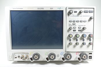
Oscilloscopes are indispensable for visualizing signal behavior over time, providing a graphical representation of amplitude versus time.
By displaying amplitude on the vertical axis and time on the horizontal axis, oscilloscopes allow you to analyze critical signal characteristics such as frequency, noise, rise time, and distortion.
These tools are especially useful in troubleshooting circuits and verifying system designs.
Features to Look For:
- Multiple channels: Compare signals from different parts of a circuit simultaneously.
- Triggering options: Stabilize waveform displays for repetitive signals, ensuring clear and consistent visualization.
- Automated measurements: Quickly determine frequency, peak voltage, rise time, and other key parameters without manual calculations.
- Storage capability: Save waveforms for later analysis or reporting.
Oscilloscopes are essential for debugging, performance testing, and understanding the dynamic behavior of electronic systems, making them a staple in any engineer’s toolkit.
Signal Generators
Signal generators are essential tools for creating precise electrical waveforms, allowing engineers to test and analyze how circuits or systems respond to known input signals.
They are particularly useful for characterizing performance, validating designs, and troubleshooting issues in both analog and digital systems.
Key features to look for:
- Frequency range: Ensure the generator supports the frequency range needed for your application.
- Output waveforms: Capability to produce a variety of waveforms such as sine, square, triangular, and custom signals.
- Amplitude control: Precise control over signal strength for accurate testing.
- Modulation options: Support for AM, FM, or pulse modulation to simulate real-world conditions.
Signal generators provide engineers with the flexibility to inject tailored signals into circuits, helping them optimize system performance and identify potential issues effectively.
Spectrum Analyzers
Spectrum analyzers are crucial tools for visualizing and measuring signal strength across a range of frequencies.
They provide insight into a signal's frequency components, allowing engineers to identify issues such as harmonics, noise, and distortion.
Key features to look for:
- Frequency range: Covers the spectrum needed for your application, from low frequencies to GHz ranges.
- Dynamic range: Detects signals with varying power levels, from weak signals to strong carriers.
- Resolution bandwidth (RBW): Determines the analyzer’s ability to distinguish closely spaced signals.
- Amplitude accuracy: Ensures precise measurements of signal strength.
Spectrum analyzers are indispensable for frequency-domain analysis, helping engineers maintain signal purity, troubleshoot issues, and optimize system performance.
Their precision and versatility make them critical for applications in RF design, telecommunications, and electronics.
Practical Considerations
When working with input signals, prioritizing accuracy and safety ensures reliable system performance and prevents potential damage to equipment.
Here are critical practices and tools to consider when handling and analyzing input signals:
Grounding and Shielding
- Grounding: Always connect the system's ground to a common reference point to prevent voltage differences that can cause unwanted noise or electrical interference.
- Shielding: Use shielded cables or enclosures to protect sensitive signals from electromagnetic interference (EMI) and radio frequency interference (RFI), which can distort measurements.
Probe Compensation
- Oscilloscope probe calibration: Ensure probes are correctly compensated before use. A mismatched probe can introduce errors, especially in high-frequency measurements. Verify the compensation of the probe using the test point on the oscilloscope, and adjust as needed.
- Selection of probes: Use the appropriate type of probe (e.g., passive, active, or differential) based on the signal type and application requirements.
Signal Conditioning
- Amplifiers: Boost weak signals to measurable levels while maintaining signal integrity.
- Filters: Remove unwanted noise or isolate specific frequency bands for focused analysis.
- Converters: Use analog-to-digital converters (ADCs) or digital-to-analog converters (DACs) when transitioning between analog and digital domains.
Cable Management
- Cable length: Minimize cable length to reduce signal attenuation and the likelihood of interference. Use high-quality cables for critical connections.
- Twisted pair and coaxial cables: Opt for twisted pair cables for differential signals or coaxial cables for single-ended signals to maintain signal quality.
Environmental Factors
- Temperature and humidity: Maintain a controlled environment to prevent signal drift caused by temperature fluctuations or moisture affecting electronic components.
- Vibration isolation: Place equipment on vibration-free surfaces to avoid mechanical interference with sensitive signal measurements.
Power Supply Considerations
- Noise-free power: Use regulated power supplies with low noise levels to avoid contaminating input signals.
- Isolation: Electrically isolate power sources from sensitive circuits to prevent ground loops and power surges.
Conclusion
Input signals are fundamental to the operation and analysis of electronic systems.
By understanding their types, characteristics, and the tools required for measurement, you can design, troubleshoot, and optimize systems effectively.
For reliable testing and measurement, access premium used oscilloscopes, spectrum analyzers, function generators, and multimeters at the Keysight Used Equipment Store—offering high-quality equipment at an exceptional value.

Whenever You’re Ready, Here Are 5 Ways We Can Help You
- Browse our Premium Used Oscilloscopes.
- Call tech support US: +1 800 829-4444
Press #, then 2. Hours: 7 am – 5 pm MT, Mon– Fri - Talk to our sales support team by clicking the icon (bottom right corner) on every offer page
- Create an account to get price alerts and access to exclusive waitlists.
- Talk to your account manager about your specific needs.
