- Introduction
- How to Use the Impedance Calculator
- What is Impedance?
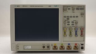
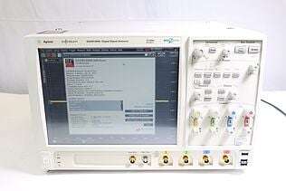
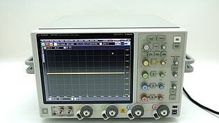
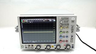
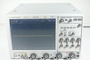
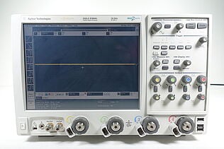
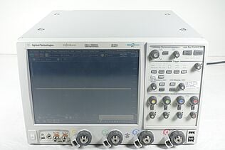
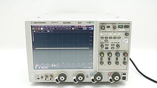
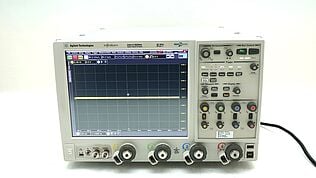
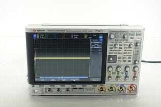
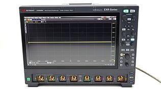
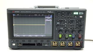
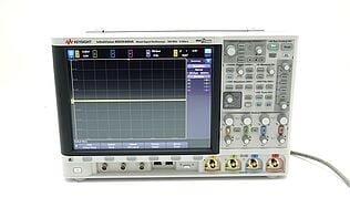
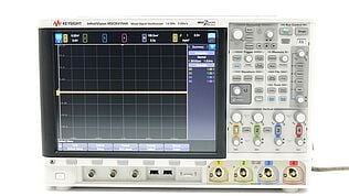
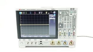
- Optimize Your Testing with Keysight’s Certified Pre-Owned Equipment
- Impedance Calculation Formulas
- Impedance in a Purely Resistive Circuit
- Impedance in a Series RL Circuit
- Impedance in a Series RC Circuit
- Impedance in a Series RLC Circuit
- Impedance in a Parallel RLC Circuit
- Impedance in a Parallel RC Circuit
- Impedance in a Parallel RL Circuit
- Factors That Can Affect Your Impedance Calculations
- Tools Compatible with the Impedance Calculator
- Real-Life Impedance Applications
- Troubleshooting and Common Issues
- Master Circuit Design with Accurate Impedance Insights
- Whenever You’re Ready, Here Are 5 Ways We Can Help You
Ever feel stuck trying to figure out why your circuit isn't working as intended? Maybe you suspect impedance issues, but calculating it can be frustrating.
Engineers often struggle with complex impedance formulas, worry about mismatched impedance causing oscillations, or feel frustrated when different impedance calculators give conflicting results. You might also be wasting precious time troubleshooting problems that accurate impedance calculations could have avoided.
An impedance mismatch can cause your audio amplifier to deliver distorted sound, your power supply to fail at peak efficiency, or your communication system to suffer from data interference. But what if calculating impedance didn't have to be a guessing game?
Imagine using a tool that helps you confidently design high-performance systems, ensuring they run as smoothly as intended. Our impedance calculator can help you achieve that.
How to Use the Impedance Calculator
An impedance calculator simplifies the process of calculating the impedance in RLC (Resistor-Inductor-Capacitor) circuits. By entering a few key parameters, you can quickly determine the impedance, phase difference, quality factor, resonant frequency, and angular frequency for either series or parallel RLC circuits. This is especially useful for engineers who want to ensure their circuits perform optimally without spending hours crunching numbers.
Step-by-Step Instructions:
- Enter Resistance (R): Type in the resistance value in Ohms (Ω). This is the resistor component of your circuit.
- Enter Inductance (L): Input the inductance value in Henries (H). This represents the inductor component, which resists changes in current.
- Enter Capacitance (C): Provide the capacitance value in Farads (F). The capacitor component stores electrical energy.
- Enter Frequency (f): Specify the operating frequency in Hertz (Hz). This is the frequency at which your circuit operates.
- Select Circuit Type: Choose either 'RLC in Series' or 'RLC in Parallel' to define your circuit configuration.
- Click 'Calculate Impedance': Hit the button to compute the impedance and other parameters.
The results will display:
- Impedance (Z): Total opposition to AC current flow.
- Phase Difference (φ): The angle between the current and voltage.
- Quality Factor (Q): Indicates the efficiency of the circuit.
- Resonant Frequency (f₀): The frequency at which inductive and capacitive reactances cancel each other.
- Angular Frequency (ω): Represents how fast the current oscillates in radians per second.
This easy-to-use tool will save you time and help you avoid common pitfalls when dealing with complex impedance calculations. Just enter your values, select your circuit type, and let the calculator do the heavy lifting!
What is Impedance?
Impedance is the measure of opposition that a circuit presents to the flow of alternating current (AC). It combines both resistance (which opposes direct current, DC) and reactance (which opposes AC) into a single value, expressed in Ohms (Ω). Unlike resistance, which remains constant, reactance varies with frequency due to inductors and capacitors in the circuit.
Impedance affects how electrical signals are transmitted, influencing everything from signal quality in communication systems to the efficiency of power supplies. Properly matching impedance ensures maximum power transfer and minimizes reflection or loss, critical for optimal circuit performance.
Optimize Your Testing with Keysight’s Certified Pre-Owned Equipment
Impedance Calculation Formulas
Impedance calculations vary depending on the components and their arrangement within the circuit. Understanding how to compute impedance for different circuit types is essential for optimizing performance and ensuring efficient power transfer.
Below, you'll find formulas and examples for each type. For a deeper dive into the formulas, check out our comprehensive impedance formula guide.
Impedance in a Purely Resistive Circuit
When only resistance (R) is present, the impedance (Z) equals the resistance:
- Formula: Z = R
- Example: For a circuit with a resistor of 10 Ω, the impedance is Z = 10 Ω.
Impedance in a Series RL Circuit
For a circuit with resistance (R) and inductance (L) in series, the impedance (Z) is:
- Formula: \(Z= \sqrt{R^2+(2 \pi fL)^2}\)
- Example: If R = 5 Ω, L = 0.01 H, and f = 60 Hz:
- Z = √(5² + (2π × 60 × 0.01)²) ≈ 6.27 Ω
Impedance in a Series RC Circuit
In a circuit with resistance (R) and capacitance (C) in series, the impedance (Z) is:
- Formula: \(Z= \sqrt{ R^2 +{1\over(2\pi fC)^2}}\)
- Example: If R = 4 Ω, C = 100 μF, and f = 50 Hz:
Z = √(4² + (1 / (2π × 50 × 100 × 10⁻⁶))²) ≈ 4.08 Ω
Impedance in a Series RLC Circuit
For a circuit with resistance (R), inductance (L), and capacitance (C) in series, the impedance (Z) is:
- Formula: \(Z= \sqrt{R^2+(2 \pi fL-{1 \over2 \pi fC})^2}\)
- Example: If R = 3 Ω, L = 0.02 H, C = 200 μF, and f = 60 Hz:
Z = √(3² + (2π × 60 × 0.02 – 1 / (2π × 60 × 200 × 10⁻⁶))²) ≈ 3.03 Ω
Impedance in a Parallel RLC Circuit
For a parallel circuit with resistance (R), inductance (L), and capacitance (C), the total impedance (Z) is:
- Formula: \(Z={1 \over \sqrt{({1 \over R^2})^2+(2 \pi fC-{1 \over 2 \pi fL})^2}}\)
- Example: If R = 10 Ω, L = 0.05 H, C = 150 μF, and f = 100 Hz:
- Z = 1 / √((1 / 10)² + ((2π × 100 × 150 × 10⁻⁶ – 1 / (2π × 100 × 0.05))²)) ≈ 6.62 Ω
Impedance in a Parallel RC Circuit
For a parallel circuit with resistance (R) and capacitance (C), the impedance (Z) is:
- Formula: \(Z={1 \over \sqrt{({1\over R})^2+(2 \pi fC)^2}}\)
- Example: If R = 8 Ω, C = 50 μF, and f = 60 Hz:
Z = 1 / √((1 / 8)² + (2π × 60 × 50 × 10⁻⁶)²) ≈ 7.98 Ω
Impedance in a Parallel RL Circuit
In a parallel circuit with resistance (R) and inductance (L), the impedance (Z) is:
- Formula: \(Z={1 \over \sqrt{( {1 \over R})^2+{1 \over (2 \pi fL)^2}}}\)
- Example: If R = 12 Ω, L = 0.1 H, and f = 50 Hz:
Z = 1 / √((1 / 12)² + (1 / (2π × 50 × 0.1))²) ≈ 10.79 Ω
By using these formulas, you can calculate the impedance of different types of circuits accurately, ensuring your designs perform as expected.
Factors That Can Affect Your Impedance Calculations
Several factors can impact the accuracy of your impedance calculations, potentially leading to circuit performance issues. Understanding these variables can help you achieve more reliable results.
- Component value tolerances: Variations in the values of resistors, inductors, and capacitors due to manufacturing tolerances can lead to discrepancies in impedance calculations. For instance, a 10% tolerance on a resistor can significantly alter the total impedance, especially in sensitive circuits. To mitigate this, select components with tighter tolerances.
- Temperature changes: Temperature variations can affect the resistance of materials and the behavior of inductors and capacitors, impacting impedance. For example, resistance increases with temperature in most materials, leading to higher impedance. Use temperature-stable components or implement temperature compensation in circuits to reduce this effect.
- Frequency variations: Impedance values can change with frequency due to the frequency-dependent nature of inductors and capacitors. Even slight frequency deviations can affect reactance and, consequently, impedance. Design your circuits to accommodate these variations or use components optimized for your operating frequency range.
- Measurement accuracy: Inaccurate tools or improperly calibrated equipment can lead to incorrect impedance measurements. Always use properly calibrated, high-quality tools and verify measurements regularly to ensure consistent and reliable results.
| Factor | Effect on Impedance | Mitigation Strategies |
| Component Value Tolerances | Causes variations in calculated impedance | Use components with tighter tolerances |
| Temperature Changes | Alters resistance and reactance values | Use temperature-stable components or compensation techniques |
| Frequency Variations | Affects reactance and impedance calculation | Design for specific frequency ranges or use optimized components |
| Measurement Accuracy | Leads to unreliable impedance calculations | Use calibrated and accurate measurement tools |
Tools Compatible with the Impedance Calculator
Using the right tools with the impedance calculator can help you verify and complement your calculations, ensuring accurate results for your circuits.
- Multimeters: Digital multimeters can measure resistance directly, allowing you to verify the resistor values used in your impedance calculations. While basic multimeters may not measure inductance or capacitance, advanced models often include these features, providing a simple check against your calculated values.
- Impedance Meters: Designed specifically to measure impedance, these meters provide precise data across a range of frequencies. They help validate the impedance values calculated for complex circuits, including those with frequency-dependent components like inductors and capacitors.
- LCR Meters: LCR (Inductance, Capacitance, and Resistance) meters measure each component's value with high accuracy. They are essential for checking individual inductance and capacitance values, which directly affect impedance calculations, particularly in AC circuits.
These tools provide the precision and reliability needed to accurately verify impedance calculations and diagnose circuit issues effectively.
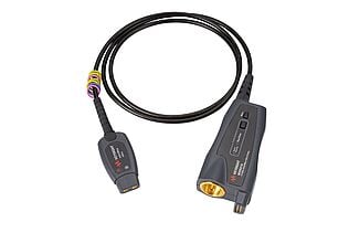
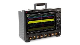
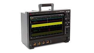
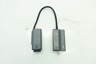
When purchasing equipment, opting for premium used or refurbished tools from a trusted provider like Keysight offers several advantages. Keysight's certified pre-owned instruments deliver the same high standards of accuracy and durability as new models, but at a lower cost.
Real-Life Impedance Applications
Impedance calculations play a crucial role in many practical applications across various fields:
- Electronics design: Impedance matching is essential when designing amplifiers, ensuring maximum power transfer and minimizing signal reflection. For instance, audio engineers use impedance calculations to design circuits that deliver clear, distortion-free sound in high-fidelity audio equipment.
- Telecommunications: In RF (radio frequency) and microwave communications, impedance matching is critical for efficient signal transmission over long distances. Designing matching networks for antennas or transmission lines requires precise impedance calculations to reduce signal loss and improve communication clarity.
- Signal processing: Engineers calculate impedance to design effective filters like low-pass, high-pass, or band-pass filters that control which frequencies pass through a circuit. This is vital in applications like noise reduction, data transmission, and audio processing.
- Power delivery optimization: Impedance calculations help optimize power delivery in circuits, such as in power supplies or converters, ensuring efficient energy transfer and minimizing losses. For example, designing a power supply for sensitive medical equipment requires careful impedance management to avoid interference and ensure consistent performance.
Accurate impedance calculations are fundamental to achieving reliable performance, efficiency, and functionality in these and many other applications.
Troubleshooting and Common Issues
When using an impedance calculator, users may encounter some issues that can lead to incorrect results or confusion:
- Incorrect inputs: Entering wrong values for resistance, inductance, capacitance, or frequency can cause inaccurate calculations. Solution: Double-check all input values against your circuit specifications to ensure accuracy.
- Misinterpretation of results: Users may misunderstand the calculated impedance, especially when dealing with complex numbers or phase differences. Solution: Familiarize yourself with impedance concepts, including the meaning of magnitude and phase, and ensure you're interpreting the results correctly.
- Misunderstanding circuit configurations: Choosing the wrong circuit type (e.g., series vs. parallel) can lead to incorrect calculations. Solution: Review the circuit diagram carefully and confirm the correct configuration is selected before calculating.
- Incorrect formula application: Using the wrong formula for the circuit type can result in errors. Solution: Ensure you apply the appropriate formula for the specific circuit configuration you are working with.
| Common Issue | Troubleshooting Steps |
| Incorrect Inputs | Double-check resistance, inductance, capacitance, and frequency values entered. |
| Misinterpretation of Results | Review impedance concepts; understand magnitude, phase, and reactance. |
| Misunderstanding Circuit Configurations | Verify the circuit type (series or parallel) matches the chosen calculator setting. |
| Incorrect Formula Application | Use the correct formula for your specific circuit configuration. |
By following these troubleshooting steps, you can avoid common pitfalls and ensure accurate impedance calculations.
Master Circuit Design with Accurate Impedance Insights
Struggling with impedance calculations can be frustrating, whether you're building a high-performance audio amplifier or optimizing a communication system. Missteps like incorrect inputs, misunderstood results, or wrong circuit configurations can lead to wasted time and unreliable circuits. But it doesn't have to be this way.
With the right tools and insights, you can confidently design circuits that perform as intended, without distortion or interference. Our impedance calculator, paired with premium, pre-calibrated equipment from Keysight, helps you overcome these obstacles, making accurate measurements accessible and affordable.
Whenever You’re Ready, Here Are 5 Ways We Can Help You
- Browse our Premium Used Network Analyzers, Oscilloscopes, Signal Analyzers and Waveform Generators
- Call tech support US: 1 800 829-4444 Press #, then 2. Hours: 7 am – 5 pm MT, Mon– Fri
- Talk to our sales support team by clicking the icon (bottom right corner) on every offer page.
- Create an account to get price alerts and access to exclusive waitlists
- Talk to your account manager about your specific needs.


