- Introduction
- Correlated Double Sampling
- Understanding the Basics
- Correlated Double Sampling in the Real World
- Benefits of Using Correlated Double Sampling in Oscilloscopes
- Boosting the Accuracy of Small-Signal, Low-Frequency Measurements
- Alleviating the Impact of Flicker Noise
- Countering Offset Voltages
- The Math Behind CDS
- Comparative Analysis
- Implementation Challenges and Solutions in Correlated Double Sampling
- Challenge 1: Need for Precise Timing
- Challenge 2: Increased Processing Power
- Challenge 3: Increased Data Throughput
- Challenge 4: Design Complexity
- Conclusion
- Whenever You’re Ready, Here Are 5 Ways We Can Help You
What if you were told that noise isn't always a negative thing in the world of signal processing? Whether you're an electrical engineer, a professional working with oscilloscopes, or a student delving into the world of electronics, the technique of Correlated Double Sampling (CDS) is sure to catch your attention.
Used widely in image sensors and oscilloscopes, CDS leverages noise to improve the accuracy of readings. Here's your comprehensive guide to understanding and using this unique and powerful technique.
Buy Oscilloscopes at a Great Discount


Need Tech Support?
Not sure which model perfectly fits your application needs? Get in touch and let our experts help you.


Select up to 3 instruments to compare
Correlated Double Sampling
Correlated double sampling is a technique applied to suppress noise, particularly in image sensors like CCD (Charge-Coupled Device) and CMOS (Complementary Metal-Oxide-Semiconductor). However, the utility of CDS isn't limited to these applications. Any scenario where "fixed pattern noise" or "1/f noise" is a hindrance, you'll find the technique useful.
Understanding the Basics
Fixed pattern noise arises from variations in the behavior of individual components in an electronic system. For example, in a CCD, each pixel might have a slightly different baseline voltage level, creating a fixed pattern that can distort the image.
Similarly, 1/f noise—also known as flicker noise or pink noise—is a type of noise with a power spectral density inversely proportional to the frequency. This means that lower frequencies have higher power, which can be a problem in electronic systems.
Correlated double sampling mitigates these types of noise by taking two samples and subtracting one from the other. Here’s a brief rundown of the process:
- First, a reset level sample is taken before the actual signal is measured.
- Then, a signal level sample is taken.
- Finally, the reset level sample is subtracted from the signal level sample.
This process effectively cancels out any fixed pattern noise, making it possible to obtain a more accurate measurement of the intended signal.
| Key Takeaway |
|---|
| Correlated Double Sampling (CDS) is a powerful signal processing technique that significantly improves the accuracy of small-signal, low-frequency measurements by reducing offset voltages and flicker noise. Despite implementation complexities, the enhanced performance and reliability it brings to electrical engineering systems, particularly in high-accuracy contexts, makes it an invaluable tool. |
Correlated Double Sampling in the Real World
In CCDs and CMOS image sensors, every pixel's value is obtained by converting the light falling on it into an electrical charge. The amount of charge is proportional to the intensity of light, and thus this charge gets converted into a voltage for processing. However, the conversion process is prone to noise and non-uniformities, and this is where CDS helps.
Benefits of Using Correlated Double Sampling in Oscilloscopes
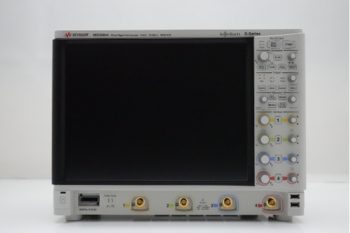
Oscilloscopes play a crucial role in electrical engineering, providing a visual representation of electrical signals and enabling real-time and automated testing. With the increasing need for precision, dealing with noise, especially in low-frequency, small-signal measurements, becomes increasingly significant. Correlated double sampling (CDS) serves as a powerful tool in this context.
Boosting the Accuracy of Small-Signal, Low-Frequency Measurements
Oscilloscopes measure a wide range of signals, from large, high-frequency waveforms to small-signal, low-frequency waveforms. However, small-signal, low-frequency measurements are often more challenging due to the potential impact of noise and offset voltages. These factors can severely distort the signal, leading to inaccurate measurements.
Correlated double sampling – taking two correlated measurements and subtracting one from the other – helps to eliminate the errors caused by the noise or offset voltages. As a result, the accuracy of the small-signal, low-frequency measurements is significantly improved, ensuring the integrity of the data captured by the oscilloscope.
Alleviating the Impact of Flicker Noise
Flicker noise, also known as 1/f noise or pink noise, is a common type of noise in electronic devices. It has a power spectral density that is inversely proportional to frequency, meaning it has more impact at lower frequencies.
In the context of oscilloscopes, flicker noise can severely impact the accuracy of low-frequency measurements. By implementing CDS, the oscilloscope is able to reduce the impact of flicker noise on the measured signal. This is achieved by subtracting a reset level sample, which includes the flicker noise, from the signal level sample, which also includes the flicker noise. The result is a cleaner signal, free from the distortions introduced by the flicker noise.
Countering Offset Voltages
Offset voltage in an oscilloscope is a constant voltage that can be added to or subtracted from the input signal, causing a shift in the output signal. This can lead to inaccuracies, particularly in small-signal measurements. Offset voltage can occur due to a variety of reasons, such as temperature variations, device aging, or manufacturing inconsistencies.
Correlated double sampling addresses the problem of offset voltages by taking a reset level sample before the actual signal is measured. Both these samples will contain the offset voltage. By subtracting the reset level sample from the signal level sample, the offset voltage gets cancelled out, providing a more precise representation of the signal.
The Math Behind CDS
The process of CDS can be simply represented mathematically:
- R + N1 (reset sample, including noise)
- S + R + N2 (signal sample, including noise)
- The subtraction process in CDS gives: (S + R + N2) – (R + N1) = S + (N2 – N1)
Here, S is the signal, R is the fixed pattern noise, and N1 and N2 are noise samples. By subtracting, we are left with the signal and the difference between two noise samples. If N1 and N2 are similar, they will largely cancel out, leaving primarily the signal.
Comparative Analysis
While correlated double sampling offers significant advantages, it's not the only technique used to reduce noise. For example, differential signaling, often used in data transmission, is another common method for rejecting noise.
Here's a comparison table of the two.
| Technique | Advantages | Disadvantages |
| Correlated Double Sampling | Reduces fixed pattern and 1/f noise | Requires extra sampling and processing |
| Differential Signaling | Rejects common mode noise, robust against external noise | Requires double the bandwidth |
Implementation Challenges and Solutions in Correlated Double Sampling
While CDS is a powerful tool in signal processing, it is not without its complexities in terms of implementation. To successfully integrate this technique into an oscilloscope or an image sensor requires a keen understanding of these potential challenges.
Challenge 1: Need for Precise Timing
- Problem: The principle of CDS relies on taking two measurements: the reset level sample and the signal level sample. This requires precise timing to ensure the samples are taken correctly and that the correlation between the noise in both samples is preserved.
- Solution: This can be managed by using a carefully designed sampling clock. Using a high-quality, stable oscillator for generating the sampling clock can ensure the timings are accurate. In addition, modern digital signal processors (DSPs) and field-programmable gate arrays (FPGAs) have features to fine-tune the timing of sampling operations.
Challenge 2: Increased Processing Power
- Problem: Implementing CDS in a system demands additional computational resources. This is because each signal requires an extra sample, and additional calculations are needed to subtract the reset level sample from the signal level sample.
- Solution: Modern DSPs and FPGAs can efficiently handle the additional computations, despite the increased complexity and power requirements. When designing a system to use CDS, it is essential to ensure that the processor has sufficient capacity to handle the additional workload.
Challenge 3: Increased Data Throughput
- Problem: CDS requires an additional sample for each signal, which doubles the amount of data the system needs to handle and store, putting more strain on the system's data throughput.
- Solution: Careful system design can mitigate this issue. This might involve using high-speed data buses, efficient data storage and retrieval systems, and optimizing the data processing algorithms to handle the increased data volume.
Challenge 4: Design Complexity
- Problem: Incorporating CDS into a system adds to the design complexity. The system needs to handle two samples for each signal and perform the subtraction operation to obtain the corrected signal.
- Solution: Using a modular design approach can help manage this complexity. The CDS functionality can be encapsulated in a dedicated module or component, simplifying the overall system design. Modern integrated circuits often include built-in CDS functionality, making it easier to include this feature in the system design.
While implementing CDS does present some challenges, these can be effectively managed with careful design and the use of modern digital processing technology. The benefits of using CDS in terms of improved signal quality and accuracy often far outweigh the challenges associated with its implementation.
Conclusion
Correlated double sampling serves as a crucial method in enhancing the precision and accuracy of measurements in image sensors and oscilloscopes. By efficiently reducing the impact of offset voltages and flicker noise, it significantly improves small-signal, low-frequency measurements.
Implementing CDS can be challenging due to the need for timing precision and more processing power. However, with careful system design and modern digital processing technology, these challenges can be effectively addressed.
Understanding and using CDS helps engineers and scientists make the most of their measurement equipment in high-stakes fields like electrical engineering, ensuring accuracy and reliability.
Now that you understand the value of CDS, you need to equip yourself with the right tools to put this knowledge into practice. Check out Keysight's Used Equipment Store for a variety of high-quality and affordable oscilloscopes, signal analyzers or network analyzers. Explore our portal today for your next precision instrument!
Browse Oscilloscopes at a Great Discount


Need Tech Support?
Not sure which model perfectly fits your application needs? Get in touch and let our experts help you.


Select up to 3 instruments to compare
Enable Notifications
In order to use this feature, you need to enable notifications.
Manage notification preferences
Whenever You’re Ready, Here Are 5 Ways We Can Help You
- Browse our Premium Used Oscilloscopes.
- Call tech support US: +1 800 829-4444
Press #, then 2. Hours: 7 am – 5 pm MT, Mon– Fri - Talk to our sales support team by clicking the icon (bottom right corner) on every offer page
- Create an account to get price alerts and access to exclusive waitlists.
- Talk to your account manager about your specific needs.

