- Introduction
- Understanding SPI
- Key Features of SPI
- How SPI Works
- Master-Slave Architecture
- SPI Communication Lines
- SPI Communication Process
- Advantages of SPI
- Disadvantages of SPI
- Comparing SPI with Other Protocols
- Testing SPI with Oscilloscopes
- Setup
- Configuration
- Analysis
- Practical Tips
- Conclusion
- Whenever You’re Ready, Here Are 5 Ways We Can Help You
Imagine you're designing a new smart thermostat. How does the main controller communicate with the temperature sensor, display screen, and Wi-Fi module all at once?
The technology behind this seamless communication is a protocol called the Serial Peripheral Interface (SPI). Widely used in embedded systems, SPI facilitates efficient interaction between microcontrollers and peripherals. For electrical engineers and technicians, understanding SPI is essential for creating and testing sophisticated devices.
Understanding SPI
SPI is a synchronous serial communication interface specification used for short-distance communication, primarily in embedded systems. It allows communication between a master device and one or more slave devices.
Key Features of SPI
- Full-duplex communication: Allows simultaneous data transmission and reception.
- Four-wire interface: Consists of MISO (Master In Slave Out), MOSI (Master Out Slave In), SCLK (Serial Clock), and SS (Slave Select).
- High-speed data transfer: Can operate at high speeds, making it suitable for applications requiring fast data rates.
| Key Takeaway |
|---|
| The Serial Peripheral Interface (SPI) is a high-speed, full-duplex communication protocol essential for efficient data transfer between microcontrollers and peripherals in embedded systems. Its simplicity and speed make it a versatile choice for short-distance communication applications. |
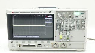
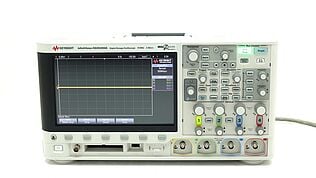
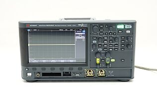
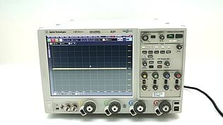
Explore Keysight’s Range of Oscilloscopes Today
How SPI Works
SPI operates on a master-slave architecture. The master device controls the communication and provides the clock signal, while slave devices respond to the master's commands.
Master-Slave Architecture
In an SPI setup, the master device initiates and controls all communication. It sends the clock signals and selects the appropriate slave device to communicate with. The slave devices wait for commands from the master and respond accordingly.
This architecture ensures that communication is well-coordinated and synchronized, allowing for efficient data exchange.
SPI Communication Lines
SPI communication relies on four key lines, each serving a specific function:
- MOSI (Master Out Slave In): This line carries data from the master to the slave. When the master wants to send data to the slave, it places the data on the MOSI line.
- MISO (Master In Slave Out): This line carries data from the slave to the master. When the slave has data to send to the master, it places the data on the MISO line.
- SCLK (Serial Clock): The master generates the clock signal on this line to synchronize data transmission. Each clock pulse allows one bit of data to be transferred.
- SS (Slave Select): The master uses this line to select which slave device to communicate with. Pulling the SS line low enables the selected slave device, while pulling it high disables it.
SPI Communication Process
The SPI communication process involves several steps to ensure data is transmitted and received accurately:
- Initialization: The master device configures the SPI clock frequency, polarity, and phase. These settings determine how data is sampled and synchronized during transmission.
- Slave selection: The master pulls the SS line of the target slave device low, indicating that it will start communicating with that specific slave.
- Data transmission: Data is transmitted from the master to the slave via the MOSI line and from the slave to the master via the MISO line. The SCLK line synchronizes this data exchange, with each clock pulse allowing one bit of data to be transferred.
- End of communication: Once the data transfer is complete, the master pulls the SS line high, deselecting the slave device and ending the communication session.
(Due to a shift towards more inclusive language, some engineers prefer the following terms: Controller instead of Master, Peripheral instead of Slave, COPI instead of MOSI, CIPO instead of MISO)
Advantages of SPI
SPI offers several benefits that make it a popular choice for embedded system communications:
- Speed: SPI supports high data rates, often in the range of tens of megahertz. This makes it suitable for applications that require rapid data transfer, such as display controllers and memory devices.
- Simplicity: The SPI protocol is straightforward to implement. With only four primary lines (MISO, MOSI, SCLK, and SS), the hardware design remains simple and cost-effective. This simplicity also extends to the software side, where the protocol's operations are easy to manage.
- Full-duplex communication: Unlike some other serial communication protocols, SPI can simultaneously transmit and receive data. This full-duplex capability doubles the efficiency of data exchange, making it ideal for applications that need continuous, two-way communication.
- Low pin count: Despite requiring four lines, SPI can communicate with multiple devices by using separate SS lines for each slave. This reduces the overall pin count on the master device, especially compared to parallel communication methods.
- Flexibility: SPI can be used with multiple slave devices by simply adding additional SS lines. This flexibility allows designers to expand their systems without significantly altering the communication protocol.
Disadvantages of SPI
Despite its advantages, SPI has some limitations that can impact its suitability for certain applications:
- No acknowledgment: SPI lacks built-in error checking mechanisms. Unlike protocols such as I2C, SPI does not provide acknowledgment bits to confirm the receipt of data. This means that additional software or hardware measures are required to ensure data integrity, increasing complexity in error-prone environments.
- Limited distance: SPI is typically used for short-distance communication within a single board or between closely located components. The high-frequency signals and lack of differential signaling make it unsuitable for long-distance communication, where signal degradation and noise can become significant issues.
- Multiple slaves complexity: Managing multiple slave devices in an SPI setup can be complex. Each slave requires a separate SS line, leading to increased pin usage on the master device. In systems with many slaves, this can become impractical, requiring multiplexing or other strategies to manage the SS lines.
- Power consumption: The continuous clock signal in SPI can lead to higher power consumption compared to protocols like I2C, which only generate clock signals during data transfer. This can be a disadvantage in power-sensitive applications where conserving energy is crucial.
Understanding these advantages and disadvantages allows you to make informed decisions when designing embedded systems, ensuring that SPI is used effectively and appropriately based on your application's specific needs.
Comparing SPI with Other Protocols
| Feature | SPI | I2C | UART |
|---|---|---|---|
| Communication | Full-Duplex | Half-Duplex | Full-Duplex |
| Number of Wires | 4 (MISO, MOSI, SCLK, SS) | 2 (SDA, SCL) | 2 (TX, RX) |
| Speed | High | Medium | Variable |
| Complexity | Simple | Moderate | Simple |
| Error Checking | No | Yes | Yes |
Testing SPI with Oscilloscopes
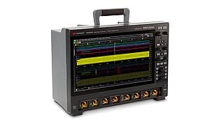
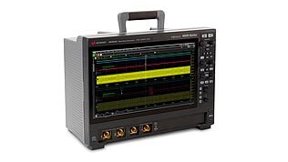
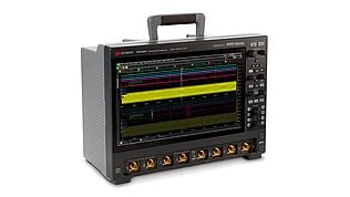
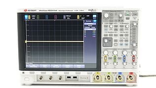
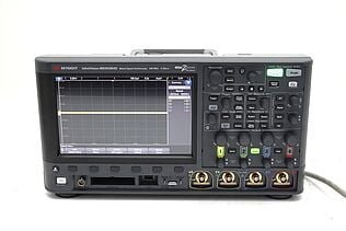
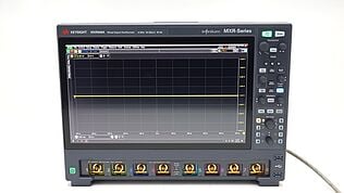
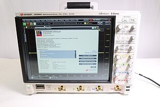
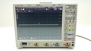
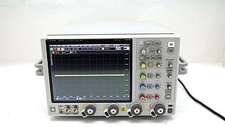
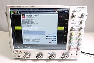
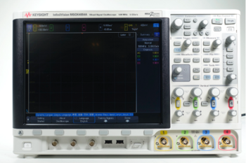
Oscilloscopes are indispensable tools for analyzing and debugging SPI signals. By capturing and displaying electrical signals, oscilloscopes allow you to visualize the communication between master and slave devices. Here’s a more detailed guide on how to use an oscilloscope for effective SPI analysis:
Setup
- Connect probes:
- MOSI (Master Out Slave In): Attach one probe to the MOSI line to monitor data sent from the master to the slave.
- MISO (Master In Slave Out): Attach a second probe to the MISO line to observe data sent from the slave to the master.
- SCLK (Serial Clock): Attach a third probe to the SCLK line to capture the clock signal provided by the master.
- SS (Slave Select): Connect a fourth probe to the SS line to see when the master selects the slave for communication.
- Ground connections: Make sure all oscilloscope probes share a common ground with the circuit under test to avoid noise and inaccurate measurements.
Configuration
- Trigger settings:
- Trigger source: Set the oscilloscope to trigger on the SCLK signal. This allows the oscilloscope to start capturing data each time a clock pulse is detected.
- Trigger type: Choose an edge trigger (rising or falling) based on the clock polarity used in your SPI setup.
- Time Base:
- Adjust time scale: Set the time scale to capture multiple clock cycles and observe entire data frames. This helps in analyzing how data bits are transmitted and received over time.
- Voltage Scale:
- Set voltage levels: Adjust the voltage scale of each channel to ensure that signal levels are appropriately displayed on the screen. Ensure the signals are within the oscilloscope’s input range.
Analysis
- Serial Decoding:
- Enable decoding: Use the oscilloscope’s serial decoding feature to interpret the SPI signals. This feature translates the electrical waveforms into human-readable binary or hexadecimal values, making it easier to understand the transmitted and received data.
- Configure protocol: Specify the protocol settings, including the clock polarity (CPOL) and clock phase (CPHA), to match the SPI configuration of your devices.
- Data Verification:
- Compare data: Verify the captured data against expected values. Check for any discrepancies that might indicate communication errors or misconfigurations.
- Timing analysis: Examine the timing relationships between MOSI, MISO, SCLK, and SS signals. Ensure that data is correctly aligned with clock pulses and that there are no timing violations.
- Signal Integrity:
- Check signal quality: Look for signal artifacts such as ringing, overshoot, or noise, which can affect data integrity. Use oscilloscope features like cursors and measurements to quantify these characteristics.
- Assess line levels: Ensure that voltage levels are within acceptable ranges for logic high and logic low states.
- Capture Multiple Frames:
- Continuous capture: Set the oscilloscope to capture multiple frames of data continuously. This helps identify intermittent issues or verify the consistency of SPI communication over time.
Practical Tips
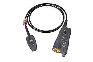
- Use high-quality probes: High-quality, low-capacitance probes minimize signal distortion and provide more accurate measurements.
- Minimize probe lengths: Keep probe leads as short as possible to reduce inductive and capacitive coupling, which can introduce noise and affect signal quality.
- Document findings: Record and document oscilloscope traces and measurements to assist in troubleshooting and future reference.
Maximize Your Budget with Keysight's Refurbished Oscilloscopes
Select up to 3 instruments to compare
Enable Notifications
In order to use this feature, you need to enable notifications.
Manage notification preferences
Conclusion
Understanding the Serial Peripheral Interface (SPI) is crucial for engineers and technicians working with embedded systems and testing equipment.
SPI offers high-speed, full-duplex communication, making it ideal for various applications. Using oscilloscopes to test and analyze SPI signals helps ensure data integrity and system reliability.
By leveraging tools like oscilloscopes, you can diagnose issues, verify data, and optimize your SPI interfaces.
For high-quality testing equipment, explore the Keysight Used Equipment Store. Shop the best premium used oscilloscopes, network analyzers,function generators, and multimeters to meet all your testing needs.

Whenever You’re Ready, Here Are 5 Ways We Can Help You
- Browse our Premium Used Oscilloscopes.
- Call tech support US: +1 800 829-4444
Press #, then 2. Hours: 7 am – 5 pm MT, Mon– Fri - Talk to our sales support team by clicking the icon (bottom right corner) on every offer page
- Create an account to get price alerts and access to exclusive waitlists.
- Talk to your account manager about your specific needs.

