- Introduction
- What is Amplitude Modulation?
- Why Do We Still Use Amplitude Modulation Today?
- Are There Limitations to Amplitude Modulation?
- AM Communication Systems
- Acoustic Signals to Sound Waves in Your Car
- Types of Amplitude Modulation
- Amplitude Modulated Wave
- Metasurfaces and Amplitude Wave Modulation
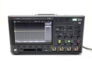
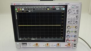
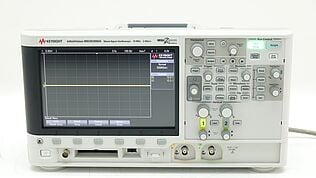
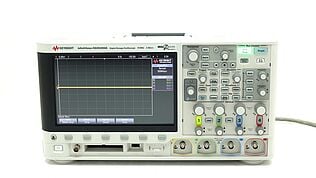
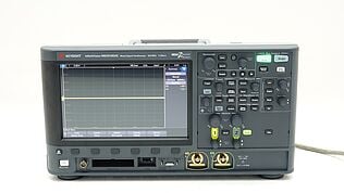
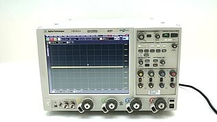
- Amplitude Modulation and Your Oscilloscope
- Oscilloscope vs. Spectrum Analyzer Amplitude
- Popular Used Oscilloscopes
What is Amplitude Modulation?
AM radio was the first type of radio communication to be used in the United States. AM stands for amplitude modulation, a technique that uses the rapid control of the amplitude or power level of a carrier wave to receive an audio signal transmitted at low frequencies.
An AM circuit is a simple amplifier used to modulate data signals. Data modulation is when information, such as a written message or image, is translated into a signal so it can be transmitted over a specific transmission medium.
This article will discuss how amplitude modulation works and what characterizes an AM circuit.
Buy Oscilloscopes at a Great Discount
What is Amplitude Modulation?
Carrier amplitude modulation is a form of signal modulation where the amplitude of the carrier wave (radio frequency signal, or RF signal) is modulated by another waveform.
With AM, the instantaneous frequency varies according to changes in amplitude of one or more input signals that represent information. Amplitude modulation occurs when a message signal modulates either the phase or the amplitude of the carrier wave.
AM is commonly used in broadcasting over radio frequencies and in various other applications such as telephony, data transmission systems that include modem, magnetic recording, and some analog video devices.
Amplitude demodulation is the complete opposite of amplitude modulation. It involves taking an incoming signal that has been modulated to its peak or peak-to-peak voltage, extracting the information contained in the waveform, and producing a digital representation by removing/reducing the carrier frequency.
| AM | FM |
|---|---|
| Signal amplitude varies continuously. | Signal is a constant amplitude, and the actual frequency varies. |
| Susceptible to noise, distortion, and interference. Difficult removal carrier signal from broadcasted info. | Can separate the carrier signal from the broadcasted information resulting in less noise, distortion, and interference. |
| Travels in a straight line and reflects off objects to reach multiple locations. | Can be blocked by obstacles such as buildings & metal objects. |
Why Do We Still Use Amplitude Modulation Today?
- AM is widely used in broadcast transmissions because it has high fidelity.
- Unlike FM, AM can be picked up with a simple tuner, which requires a complex demodulator.
- AM signals are more susceptible to noise.
Are There Limitations to Amplitude Modulation?
Yes, there are some limitations to using amplitude modulation.
- AM signals are subject to noise, so they don’t work well with long distances or low-quality audio equipment.
- The process wastes power because it broadcasts over multiple channels by adding additional baseband frequency components to the signal.
AM Communication Systems
An AM communication system is a network of devices that use amplitude modulation to transmit and receive information.
The World Radiocommunication Conference (WRC) sets the standards for electromagnetic radiation. For decades, it has defined peak-to-peak voltage relationships to the amount of information transmitted over a given frequency range.
For example: : If you habve a carrier wave with a frequency of 100 MHz and a peak-to-peak voltage of 1 volt, any changes in voltage +/- one volt would cause information to not be transmitted.
At this point, the only way to transmit more data is through amplitude modulation.
Acoustic Signals to Sound Waves in Your Car
Power calculation in AM radio is a process of converting the power from a radio station to the desired amplitude, allowing people to listen with their car radios or home AM radios. This conversion is done via an "envelope detector," which detects the envelope of the signal and outputs it as an audio waveform.
You can measure the AM modulation depth or AM modulation index with an oscilloscope. To do this, set up the input to be a sine wave, set the vertical scale voltage/division to 5 volts per division, and hook up your probe to one of the outer rings on an AM radio antenna.
For a more in-depth explanation of how to use your oscilloscope, check out Oscilloscope Basics.
Which Circuit Uses Amplitude Modulation?
AM uses one wave to vary the strength of another. The resulting wave has different characteristics, depending on which method you use and the types of waves it works with.
For example, there are several ways to produce amplitude modulation, such as:
- Phase modulation
- Frequency modulation
- Impedance modulation
Each type can be used for a wide variety of purposes, including digital radio broadcasting or sending faxes over phone lines.
Types of Amplitude Modulation
- Single-sideband modulation (SSB) is a form of amplitude modulation (AM) that is used to transmit information. In the most common SSB application, only one sideband of the modulated carrier wave is transmitted.
The term "single-sideband" has come to mean that only one of the two possible sidebands and their mirror images, or "upper" and "lower" sidebands, is transmitted.
A carrier wave of a specific frequency transports an information-bearing signal; in the case of SSB transmission, this carrier is suppressed and the transmission consists only of the upper or lower sideband, plus enough of the other sideband to transmit all necessary information. - Hum modulation is a term that refers to the background noise or “hum” that you sometimes hear when using an AM radio.
The device’s antenna captures the carrier wave from the station and propagates it through its internal circuitry, which can be disrupted by various factors such as stray signals, inductive loads, etc. This distorts the information being sent, resulting in a low-frequency hum. - QAM (Quadrature AM) is a digital communication technique that uses two carrier waves, in-phase and quadrature, to carry data. It’s a common method for transmitting information, used in everything from TV broadcasts to WiFi signals.
Amplitude Modulated Wave
An amplitude-modulated wave is a carrier wave that has been made to convey more information by increasing and decreasing its peak-to-peak value.
The voltage or current used to represent a "1", for example, can be set at a greater level than the voltage or current used to represent a "0" by changing the amplitude of the carrier wave based on your input signal. By varying the amplitude of a carrier wave, you can produce more information and thus transmit more data than would be possible through other means.
What is Peak-to-Peak Amplitude?
Peak-to-peak amplitude refers to the absolute value of a signal’s maximum voltage.
For example: If you had a sine wave with an amplitude of 10 V, its peak-to-peak amplitude would be 20 V (10 is the highest point on the waveform, and 20 is twice as high).
Most oscilloscopes can measure peak-peak voltage in addition to average (RMS)
voltage by introducing additional circuitry for this purpose.
Metasurfaces and Amplitude Wave Modulation
Metasurfaces are artificial structures that can control the propagation of electromagnetic waves by altering their phase, polarization, amplitude, and more
For example, by using metasurfaces atop an antenna to control the wave’s behavior, you could better cancel noise or reduce interference by 20 dB (ten times less than 10 log[10]).
Amplitude Modulation and Your Oscilloscope
The amplitude accuracy of an oscilloscope is how close the display’s vertical axis (Y-axis) corresponds to the input waveform’s actual voltage. Standard deviation is used to measure the amplitude of a waveform. The larger the standard deviation, the more spread-out the waveform.
For example: If you were using a 10X probe with a 100 MHz carrier wave and displayed it on an oscilloscope, any changes in voltage greater than ±0.1 V would be displayed as ±10V. This is due to the Y-axis being magnified by a factor of 10 through X-Y mode. The closer your display matches the input signal, the better the accuracy measuring that signal's characteristics, such as frequency or power.
Browse Oscilloscopes at a Great Discount
Select up to 3 instruments to compare
Enable Notifications
In order to use this feature, you need to enable notifications.
Manage notification preferences
Oscilloscope vs. Spectrum Analyzer Amplitude
Oscilloscopes were originally designed to measure the amplitude of electronic signals, but they’ve been used for a wider variety of purposes over time.
On the other hand, spectrum analyzers are generally built with inputs that have high bandwidth and low noise floor to accurately measure signal characteristics, including power and frequency.
When you connect an oscilloscope to a spectrum analyzer through its input channels, you’re able to see amplitude (signal strength) displayed on the oscilloscope and frequency or spectral information displayed on the spectrum analyzer. This can allow you to analyze signals such as SDR IQ data on your computer using only two instruments instead of several.
To learn more about the features of used Keysight Oscilloscopes and to see the wide variety of products we sell at discounted rates, visit Keysight Used Equipment.

Subscribe to Get Our Latest News, Updates, and Articles.
Popular Used Oscilloscopes
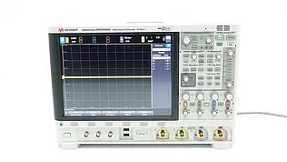
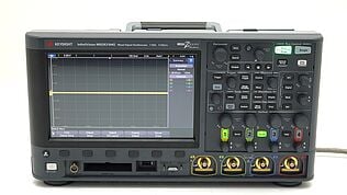
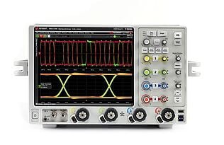
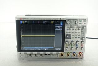
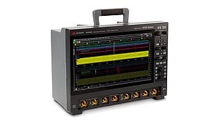
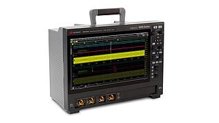
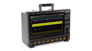
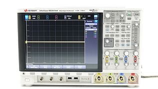
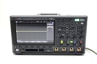
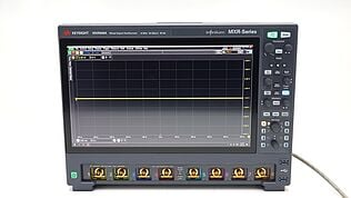
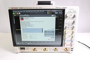
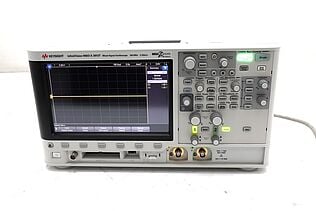
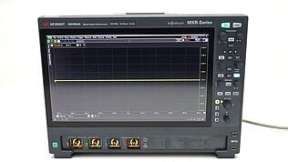
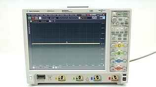
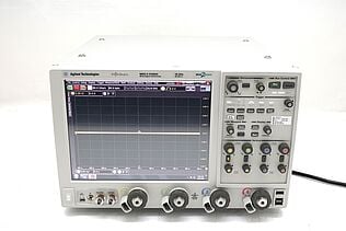
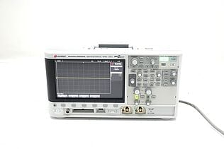
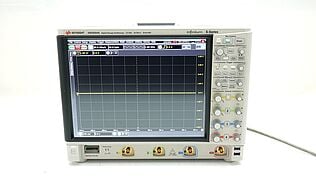
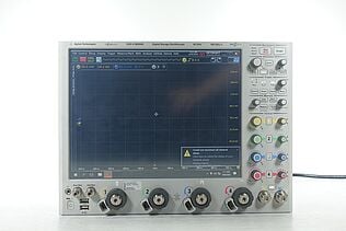
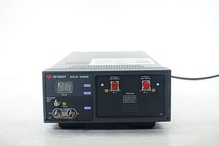
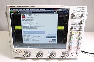
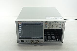
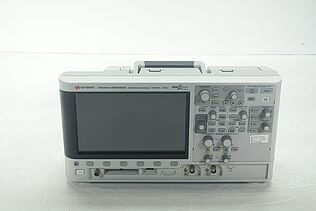
Keysight Used Oscilloscopes offers a wide range of industry leading pre-owened oscilloscopes, ranging from older generation Agilent oscilloscopes to the newest Keysight oscilloscope models. So whether you are a fist time buyer, replacing a model like-for-like or looking for upgrade – we have something for you.
