- Introduction
- TL;DR
- Understanding the Basics of Z-Transform
- The Z-Transform Formula
- Z-Transform and Signal Processing
- Z-Transform in Oscilloscopes and Signal Generators
- Common Misconceptions About Z-Transform
- Practical Applications of Z-Transform
- Z-Transform Calculations and Measurements
- The Future of Z-Transform in Electrical Engineering
- Why Choose Keysight for Your Electrical Engineering Needs
- Glossary of Terms
- Final Thoughts
- Whenever You’re Ready, Here Are 4 Ways We Can Help You
이 페이지는 현재 한국어가 제공되지 않습니다. 빠른 시일 내에 더 많은 콘텐츠 제공과 함께 한국어 지원을 할 예정이오니 조금만 기다려 주십시오.
투표해 주셔서 감사합니다."Mastering the Z-Transform formula is akin to acquiring a powerful lens that brings the intricate universe of digital signal processing into sharp focus. It is an indispensable tool for electrical engineers and forms the core of modern telecommunications systems and digital electronics." -Dr. Helen Czerski, Professor of Electrical Engineering & Signal Processing.
Consider a scenario where you are an electrical engineer involved in a major telecommunications project. Your role is to ensure the seamless transfer of data – be it emails, videos, or phone calls – across different regions. To ensure that these signals are transmitted without delay or distortion, the Z-Transform formula plays a crucial role.
So, what is the formula, and why is it so critical in electrical engineering? Let's explore this mathematical tool and understand its significance. This guide provides a comprehensive insight into the Z-Transform equation, highlighting its significance in electrical engineering with practical examples.
TL;DR
- The Z-Transform formula is a fundamental tool in electrical engineering, particularly for signal processing, allowing for the analysis of discrete, finite signals by converting time-domain signals into frequency-domain representations.
- To ensure proper understanding of the Z-Transform, it is essential to clarify prevalent misunderstandings, such as mistaking it for the Fourier Transform or assuming it solely applies to stable systems.
- The Z-Transform has extensive applications in electrical engineering, including the design of electronic circuits and equipment like signal generators and oscilloscopes.
- Future advancements in Z-Transform research will play a significant role in the evolution of electrical engineering, especially as we delve further into the digital age.
- Familiarity with the symbols, terms, and units used in Z-Transform formulas is necessary for effectively applying the concept.
Understanding the Basics of Z-Transform
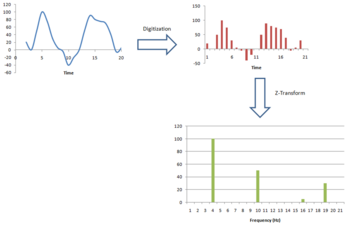
The Z-Transform is a mathematical technique used in the field of signal processing and system analysis. It is a discrete-time equivalent of the Laplace Transform (deals with continuous time signals) and is particularly useful when dealing with digital signals. In its most basic form, the Z-Transform changes a discrete time-domain signal, which is naturally sequential into a continuous frequency-domain signal.
In signal processing and electrical engineering, the Z-Transform plays an indispensable role. It simplifies working with digital signals by analyzing them in the frequency domain instead of the time domain. This is useful in various applications such as signal detection, system identification, and filter design.
| Key Takeaway |
|---|
| The Z-Transform is a cornerstone concept in signal processing, and it's used to manipulate and analyze discrete, finite signals. |
The Z-Transform Formula
The Z-Transform of a discrete time signal x[n] is generally represented as:
X(z)=10∑n=−∞x|n|z−n
Where:
- Σ denotes the sum from n=-∞ to n=+∞.
- x|n| is the discrete time-domain signal.
- z is a complex number, where z = rejω, (r and ω are real numbers).
The components of the Z-Transform formula hold the following significance:
- x|n|: This is the time-domain signal – the actual data sequence you are trying to analyze or manipulate.
- z^-n: This is the complex exponential part of the formula that allows us to transform our time-domain signal into the frequency domain. z is a complex number that provides the link between the discrete time domain and continuous frequency domain.
| Component | Significance |
| X(z) | This is the Z-transform of the discrete-time signal x[n]. It is a function of the complex variable z. |
| Σ | This is the summation symbol. It tells us that we need to sum the expression to its right for all values of n, integers from -∞ to +∞. |
| x|n| | This is the discrete time-domain signal that we wish to transform. The square brackets indicate that it is a function of the discrete variable n. |
| z | This is a complex number (re^jω), crucial for the Z-transform as it provides a link from the discrete time domain to the continuous frequency domain. |
| z^-n | This is the complex exponential part of the formula that allows us to transform our time-domain signal into the frequency domain. The exponent -n essentially introduces a delay or advance in the time-domain signal. |
Z-Transform and Signal Processing
The Z-Transform and signal processing are intrinsically linked. In the field of signal processing, a primary challenge is understanding the behavior of discrete-time systems. These systems are characterized by their response to input signals over time. The Z-Transform allows us to convert these time-based sequences into algebraic functions that are easier to analyze and manipulate.
In signal analysis, the Z-Transform is commonly used for the examination of digital systems. It facilitates the translation of a discrete-time signal into a complex frequency domain representation. This transformation is advantageous because it converts convolution operations into multiplication operations, greatly simplifying the analysis of the system.
Moreover, the Z-Transform provides a framework for understanding and predicting the behavior of digital filters, a crucial aspect of signal processing. Z-Transform helps engineers design and optimize filters with better accuracy by showing the system's frequency response visually.

| Key Takeaway |
|---|
| The Z-Transform is a pivotal tool in signal processing, enabling engineers to effectively analyze and manipulate signals by converting complex time-domain problems into simpler frequency-domain ones. It enhances the analysis of digital systems, and aids in the design and optimization of digital filters. |
Z-Transform in Oscilloscopes and Signal Generators
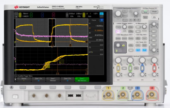
Z-Transform plays a vital role in the functioning and operation of devices like oscilloscopes and signal generators. In the field of electrical engineering, these tools play a crucial role as they are designed to generate and display signals in both the time and frequency domains.
The Z-transform is a powerful tool used in oscilloscopes for analyzing discrete signals. This representation provides a unique viewpoint of signal characteristics in the frequency domain. This can be particularly useful when looking at the spectral components of a signal, or when investigating properties such as phase and magnitude at different frequencies.
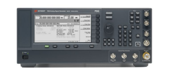
Signal generators, on the other hand, often employ the Z-Transform during the design phase. When creating a digital filter for a signal generator, engineers use the Z-Transform to analyze and optimize the performance of a digital filter in the frequency domain before implementing it in the time domain.
| Device | Use of Z-Transform |
| Oscilloscope | The Z-Transform enables frequency domain analysis of captured discrete signals, providing insight into phase and magnitude across different frequencies. |
| Signal Generator | During the design process, digital filters can be optimized for signal generation by using the Z-Transform, which enables frequency domain analysis prior to implementing changes in the time domain. |
Steps to apply the Z-Transform in oscilloscopes and signal generators:
- Identify the discrete signal you want to analyze. In an oscilloscope, this would be the captured signal. In a signal generator, this might be the desired output signal of a digital filter.
- Apply the Z-Transform to the discrete signal to convert it into the frequency domain.
- Analyze the transformed signal to gain insights. In an oscilloscope, look at spectral components, phase, and magnitude at various frequencies. In a signal generator, analyze the frequency response of the digital filter.
- Use the findings from the frequency domain analysis to adjust your signal. In an oscilloscope, this might involve filtering out certain frequencies. In a signal generator, this could involve adjusting the parameters of your digital filter.
- If using a signal generator, implement the optimized digital filter and use it to generate your desired signal.
Common Misconceptions About Z-Transform
Like many complex mathematical concepts, there are several misconceptions about the Z-Transform. Here are three common ones:
Misconception: Z-Transform and Fourier Transform are the same.
Correction: While both the Z-Transform and Fourier Transform are used to analyze signals, they are not the same. The Z-Transform is more general and can handle a wider variety of signals, especially those of discrete and finite nature. The Fourier Transform, on the other hand, is more suited for continuous and infinite signals.
Misconception: Z-Transform is only applicable to stable systems.
Correction: The Z-Transform can be applied to both stable and unstable systems. For stable systems, all the poles of the Z-Transform lie inside the unit circle, while for unstable systems, one or more poles lie outside the unit circle. Therefore, it can provide insights into the stability of a system.
Misconception: Z-Transform is only relevant in electrical engineering.
Correction: While Z-Transform is extensively used in electrical engineering, it's also applicable in many other disciplines that deal with digital signals and discrete systems. This includes fields like digital communications, control theory, seismology, and even economics.
Common misconceptions about Z-Transform and their corrections:
- Z-Transform and Fourier Transform are the same. (They are not; each has its own specific applications and characteristics.)
- Z-Transform is only applicable to stable systems. (It can be applied to both stable and unstable systems.)
- Z-Transform is only relevant in electrical engineering. (It's widely used in many other fields that deal with digital signals and discrete systems.)
| Key Takeaway |
|---|
| Several misconceptions surround the Z-Transform, but a clear understanding of its true nature and scope can significantly enhance your proficiency in signal processing and beyond. |
Practical Applications of Z-Transform
The Z-Transform has widespread practical applications, especially in the design of electronic circuits and appliances. It helps engineers develop efficient and optimized circuits, with applications ranging from household devices like digital equalizers in audio systems, to complex scientific instruments like signal generators and oscilloscopes.
One everyday example is the use of the Z-Transform in digital television receivers. These receivers often employ digital filters to decode incoming signals and convert them into images. The Z-Transform is used to analyze and optimize these filters, ensuring they provide the best possible image quality.
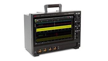
In signal generators and oscilloscopes, the Z-Transform is used to analyze the behavior of digital filters. It provides an efficient way to examine the filters' frequency response, which aids in their design and optimization.
Steps to apply the Z-Transform in practical applications:
- Identify the discrete signal that you want to analyze. This could be a signal captured by an oscilloscope or a signal you want to generate with a signal generator.
- Apply the Z-Transform to the signal to convert it into a frequency-domain representation.
- Use the frequency-domain representation to analyze the signal. You could examine the phase and magnitude at various frequencies or the frequency response of a digital filter.
- Use the insights gained from your frequency-domain analysis to improve your signal. You could design or adjust a digital filter, or modify the parameters of a signal generator.
| Key Takeaway |
|---|
| The Z-Transform is a powerful tool in the design and analysis of electronic circuits, from household appliances to advanced scientific instruments. Its ability to convert time-domain signals into the frequency domain aids in the design and optimization of electronic systems. |
Z-Transform Calculations and Measurements
Calculating the Z-Transform is a crucial aspect of signal processing. It is an intricate process, requiring both mathematical precision and a sound understanding of the discrete signals involved. Various tools can aid in this calculation, ranging from mathematical software packages to specialized calculators.
Accurate Z-Transform calculations are vital for precise signal analysis. They provide accurate insights into the signal's characteristics, which in turn can inform decisions on filter design, system analysis, and other signal processing tasks.
| Tool | Use for Z-Transform | Accuracy |
| MATLAB | MATLAB is an extensively used programming language for scientific computing. It has built-in functions to compute Z-Transforms directly. | High |
| Python (with libraries like NumPy, SciPy) | Python, coupled with its scientific computing libraries, provides functions to calculate the Z-Transform. | High |
| Mathematica | Mathematica, a computational software program, offers precise computation of the Z-Transform. | High |
| Hand Calculation | Though not a tool per se, Z-Transforms can be calculated by hand for simpler signals, using standard mathematical techniques. | Varies based on the complexity of the signal and the mathematical skill of the individual. |
Tips for accurate Z-Transform calculations:
- Ensure a clear understanding of the properties of the Z-Transform, including linearity, time shifting, and convolution.
- Validate calculations with multiple tools when possible, such as cross-checking hand calculations with a software package like MATLAB.
- Carefully manage the region of convergence (ROC) in your calculations as it determines the stability of the system.
- Remember to account for initial conditions in differential equations when performing a Z-Transform.
- Double-check all calculations for errors, as even minor mistakes can drastically affect the final result.
The Future of Z-Transform in Electrical Engineering
The Z-Transform is an enduring and pivotal component of electrical engineering, and its importance is set to grow with emerging trends in the field. One such trend is the continued growth of digital systems and the consequent need for improved signal processing techniques.
As the digital revolution continues, we can expect more complex and sophisticated digital signals. The Z-Transform, with its ability to convert time-domain signals into frequency-domain representations, will be indispensable in analyzing these signals. Furthermore, advancements in computational power and algorithms may also enable more complex and accurate Z-Transform calculations, further enhancing its utility.
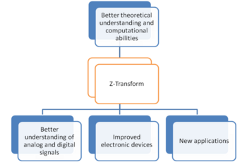
Predictions for the future of Z-Transform in electrical engineering:
- Increased use of Z-Transform in the analysis of complex digital signals as digital systems continue to evolve.
- Improved computational capabilities, allowing for more sophisticated and accurate Z-Transform calculations.
- Continued integration of Z-Transform principles in the design of electronic devices, from household appliances to scientific instruments.
- Advances in Z-Transform research, potentially uncovering new applications in emerging fields like quantum computing or neuromorphic engineering.
| Key Takeaway |
|---|
| The future of electrical engineering will undoubtedly be influenced by advancements in Z-Transform research and its applications. As our digital world continues to grow, so will the importance of this critical tool in signal processing. |
Why Choose Keysight for Your Electrical Engineering Needs
When it comes to electrical engineering tools and services, Keysight stands out as a trusted partner for many professionals. Offering a vast selection of high-quality used equipment, Keysight ensures you get reliable and efficient devices at a fraction of the cost of new ones.
These pre-owned tools go through rigorous testing and refurbishment processes, ensuring they meet the original equipment manufacturer (OEM) standards. As a result, you can be confident that the equipment you receive will perform to the highest standards.
Keysight offers unique calibration services that set them apart in the industry. Their calibration services also include adjustments, repairs, and performance verification, providing a comprehensive solution to maintain the reliability and accuracy of your equipment.
| Key Takeaway |
|---|
| Keysight offers an unparalleled combination of high-quality used equipment and unique calibration services, setting them apart in the industry. Choosing Keysight means opting for reliability, precision, and a partner committed to meeting your electrical engineering needs. |
Glossary of Terms
Understanding the symbols and units used in Z-Transform formulas is critical to grasping the concept and applying it effectively. Here's a brief glossary of terms related to the Z-Transform:
| Term | Definition | Example |
| Discrete-time signal | A signal that is defined or only exists at discrete points in time. | A digital audio recording is a discrete-time signal, as it only captures the sound at specific, discrete intervals. |
| z | The complex variable in the Z-Transform. | In the formula X(z) = Σ x[n]z⁻ⁿ, z is the complex variable. |
| ROC (Region of Convergence) | The set of values of z for which the Z-Transform converges to a finite value. | In a stable system, the ROC is the area where all poles of the Z-Transform lie inside the unit circle. |
| Pole | A value of z that causes the denominator of a Z-Transform expression to become zero. | If X(z) = 1 / (1 – az⁻¹), the pole is z = a. |
| Zero | A value of z that causes the numerator of a Z-Transform expression to become zero. | If X(z) = (1 – az⁻¹), X(z) is zero if z = a. |
Final Thoughts
The Z-Transform, with its formula X(z) = Σ x|n|z⁻ⁿ, serves as an indispensable tool for electrical engineers, particularly in the realm of signal processing. It offers a means to transform complex time-domain signals into the frequency domain, facilitating the analysis of digital systems.
From enhancing the design of electronic circuits, and debunking misconceptions, to its crucial role in various digital appliances and devices, the Z-Transform is central to the evolving field of electrical engineering.
With Keysight's pre-owned equipment and calibration services, engineers are equipped with high-quality, reliable tools needed to apply their Z-Transform knowledge effectively. Our used store not only offers devices at a fraction of the cost of new ones but also guarantees that they meet OEM standards, ensuring you always get the best product.
We encourage you to explore Keysight's used store for more resources and tools, specially curated for the needs of today's electrical engineers. As the industry moves forward, we are committed to providing you with the tools and support you need to stay ahead.

Whenever You’re Ready, Here Are 4 Ways We Can Help You
- Browse our Premium Used Equipment.
- Call tech support US: 1 800 829-4444
Press #, then 2. Hours: 7am – 5pm MT, Mon– Fri - Talk to our sales support team by clicking the icon (bottom right corner) on every offer page
- Talk to your account manager about your specific needs
