- Introduction
- Definition of VSWR
- TL;DR
- Understanding the Basics of VSWR
- The Reflection Coefficient and Impedance Mismatch
- Signal Power and Return Loss
- Signal Power and Mismatch Loss
- Loss in Decibels (dB) and Return Loss Measurement
- VSWR and Return Loss in Oscilloscopes and Signal Generators
- Glossary of Terms
- Why Choose Keysight for Your Wireless Communication Needs
- Final Thoughts from the Keysight Used Store
- Whenever You’re Ready, Here Are 5 Ways We Can Help You
- Popular Used Oscilloscopes
Definition of VSWR
"Understanding VSWR isn't just about crunching numbers; it's about shaping the future of efficient wireless communication." – Dr. Bernard Sklar, Communications Engineer and author.
Picture this: an electrical engineer is in a bustling laboratory, running complex tests on an advanced radio frequency (RF) system. Amidst a sea of figures and data, they pause on one particular metric: the Voltage Standing Wave Ratio (VSWR). This might seem like just another number to the untrained eye, but to the engineer, it's a key indicator of how efficient, reliable, and successful their system can be.
VSWR, along with return loss, is a pivotal parameter in the realm of electrical and RF engineering. They are important for evaluating the efficiency of power transfer in various applications, such as designing telecommunication networks and ensuring the reliability of radar systems.
In this highly technical and exacting field, having precise tools like a VSWR/return loss calculator at one's disposal is a necessity. A fine-tuned understanding of these metrics can guide an engineer to enhance system performance, optimize power transmission, and develop breakthrough solutions. Let's delve deeper into these core concepts, and discover how a simple calculator can significantly improve your engineering endeavors.
TL;DR
- VSWR (Voltage Standing Wave Ratio) and return loss are crucial parameters in signal transmission, impacting system efficiency and power transfer. They help analyze impedance mismatches and signal reflections in an electrical system.
- Understanding the concepts of reflection coefficient and impedance mismatch is key to managing reflections and improving system efficiency. These concepts are especially important in designing and optimizing RF and telecommunication systems.
- Tools such as network analyzers, reflectometers, and return loss meters are used to measure VSWR and return loss, providing insights into system performance and areas for improvement.
- The application of VSWR and return loss concepts is essential in the use of tools such as oscilloscopes and signal generators, leading to more accurate testing and analysis.
- Keysight's tools and services, including their antenna gain calculator, Vector Network Analyzers, and Spectrum Analyzers, offer precise, user-friendly solutions for wireless communication professionals. These tools can help improve the application of VSWR and return loss knowledge, enhancing system performance and efficiency.
Understanding the Basics of VSWR
When it comes to signal transmission and electrical engineering, the role of VSWR, or Voltage Standing Wave Ratio, is paramount. This crucial metric provides a quantifiable measure of a system's efficiency in transmitting power, effectively becoming the heart of any RF and telecommunication setup.
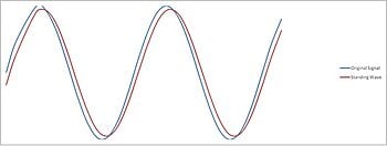
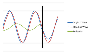
So, what is VSWR exactly? At its core, VSWR is a ratio. It's a measure of the maximum voltage to the minimum voltage in a standing wave pattern along a transmission line, such as a coaxial cable. If you were to visualize this, you would see a wave along the transmission line with peaks (maximum voltage) and troughs (minimum voltage). The VSWR is the ratio of these peak and trough values.
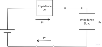
In simpler terms, VSWR is a reflection of how well the impedance of the load (like an antenna) matches the impedance of the transmission line itself. A low VSWR indicates a better match, meaning less signal reflection and more power delivered to the load – and that's what we want for efficient signal transmission.

| Key Takeaway |
|---|
| VSWR is the crux of power transfer efficiency in electrical systems. Mastering the concept of VSWR is like holding a compass that guides you towards an optimal and successful RF design. |
The Reflection Coefficient and Impedance Mismatch
Let's dig a bit deeper into the intricacies of signal transmission, specifically the concept of the reflection coefficient, often symbolized as Gamma (Γ). The reflection coefficient is a complex number that describes how much of an electromagnetic wave is reflected by an impedance discontinuity in the transmission line. It's derived from the ratio of the reflected wave amplitude to the incident wave amplitude. A value of zero signifies no reflection, i.e., perfect impedance match, while a value of one denotes total reflection.
The reflection coefficient is intrinsically tied to the phenomenon of impedance mismatch. Essentially, when the load impedance doesn't exactly match the source or transmission line impedance, we have an impedance mismatch. This mismatch can lead to signal reflections, resulting in power loss and reduced system efficiency.
Factors affecting impedance mismatch and their impact on the reflection coefficient include:
- Mismatched components: If components connected in a system have significantly different impedance values, it can result in a larger mismatch, increasing the reflection coefficient.
- Frequency changes: Impedance values can vary with frequency. Thus, a change in operating frequency can cause a change in the reflection coefficient.
- Temperature variations: Physical properties of materials can change with temperature, affecting their impedance and consequently the reflection coefficient.
- Load variations: Changes in load conditions can alter the load impedance, leading to a mismatch and higher reflection coefficient.
Understanding these factors and managing impedance mismatch is crucial as it directly impacts the reflection coefficient and thereby the overall performance of the electrical or RF system.
Signal Power and Return Loss
In the world of signal transmission and electrical engineering, another key concept to grasp is return loss. This term provides a measure of how much power is lost when it's reflected back due to impedance mismatches in the transmission line. Return loss is defined in decibels (dB) and represents the ratio of incoming power to the reflected power. A higher return loss value is desirable as it indicates a lower level of reflected power and a better impedance match.
The relation between return loss, VSWR, and the reflection coefficient provides a comprehensive view of the system's efficiency. Specifically, return loss is related to the reflection coefficient (Γ) as follows: Return Loss (dB) = -20 log10|Γ|.
On the other hand, VSWR and the reflection coefficient are connected by the equation: VSWR = (1+|Γ|)/(1-|Γ|).
By understanding these relationships, you can gain insights into how much power is being effectively utilized and how much is being wasted due to reflections. This understanding can guide strategies to minimize reflections, improve impedance matching, and thereby increase the system efficiency.

| Key Takeaway |
|---|
| Return loss, in relation with VSWR and the reflection coefficient, serves as a vital benchmark in gauging system performance. A solid understanding of return loss can lead engineers to craft more efficient and reliable signal transmission systems. |
Signal Power and Mismatch Loss
An essential concept that often comes into play in signal transmission is Mismatch Loss. Simply put, Mismatch Loss quantifies the reduction in power at the output due to impedance mismatch. It's measured in decibels (dB) and signifies how much power is wasted when the load impedance doesn't match the transmission line impedance.
When an impedance mismatch occurs, a portion of the signal power gets reflected back towards the source rather than being absorbed by the load. This results in loss of power that could have otherwise been usefully employed, thereby reducing the system's overall efficiency. Consequently, the impact of Mismatch Loss is crucial in designing and optimizing RF and telecommunication systems.

Steps to minimize mismatch loss in signal transmission:
- Ensure Component Compatibility: When designing a system, ensure that the components used have compatible impedance values. The impedance of every device and transmission line used should closely match the system impedance to reduce reflections and Mismatch Loss.
- Impedance Matching Techniques: Use impedance matching devices or techniques, such as stubs, transformers, or tuning elements. These devices can help match the load impedance with the source or transmission line impedance.
- Careful Frequency Selection: Since impedance values can change with frequency, carefully select the operating frequency to ensure impedance match.
- Regular System Testing: Regularly test your system to identify any changes in impedance values due to component aging, environmental changes, or other factors. Early detection of such changes can help minimize mismatch loss.
By following these steps, engineers can effectively limit Mismatch Loss, improving the efficiency and performance of their signal transmission systems.
Loss in Decibels (dB) and Return Loss Measurement
In the realm of signal transmission, return loss is a key metric used to indicate how much power is reflected back to the source due to impedance mismatches. It's defined as the ratio of the power of the incoming signal to the power of the reflected signal, measured in decibels (dB). A higher return loss value implies less reflected power and better impedance matching, which is desirable for system efficiency.
To measure return loss, engineers typically use a variety of tools and techniques, including network analyzers, reflectometers, and dedicated return loss meters. These devices function by transmitting a known signal into the system and measuring the power of the signal that gets reflected back.
Different Tools for Measuring Return Loss and Their Accuracy:
| Tool | Accuracy |
|---|---|
| Network Analyzer | Highly accurate |
| Reflectometer | Moderate to high accuracy |
| Return Loss Meter | Moderate accuracy |
While a network analyzer is often seen as the gold standard due to its high accuracy and versatility, reflectometers and return loss meters also offer reliable measurements and are commonly used in many applications. The choice of tool largely depends on the specific requirements of the system, the available resources, and the level of accuracy needed.
VSWR and Return Loss in Oscilloscopes and Signal Generators
In the world of electronics, oscilloscopes and signal generators are fundamental tools that engineers rely on to test and analyze circuits. VSWR and return loss are key parameters in the context of these devices, significantly impacting their performance and efficiency.
In oscilloscopes, VSWR and return loss play crucial roles in maintaining signal integrity. They help to understand and control reflections and signal distortions that might occur due to impedance mismatches between the device under test and the oscilloscope.
In signal generators, these parameters are important for ensuring the proper transmission of the generated signal to the device under test. A well-matched system, indicated by a low VSWR and high return loss, ensures that most of the generated signal reaches the device, leading to accurate and reliable testing.
Application of VSWR and Return Loss in Oscilloscopes and Signal Generators:
| Device | Use of VSWR | Use of return loss |
| Oscilloscope | Control signal reflections and distortions | Maintain signal integrity during measurements |
| Signal Generator | Ensure effective signal transmission | Maximize power delivered to the device under test |
| Key Takeaway |
|---|
| Mastering the concepts of VSWR and return loss can empower engineers to significantly enhance the performance and efficiency of oscilloscopes and signal generators, leading to more accurate testing and analysis. |
Glossary of Terms
In the discussion of VSWR and return loss, a number of terms, symbols, and units repeatedly come up. Let's take a moment to clarify these terms to enhance understanding and application of these key concepts.
VSWR (Voltage Standing Wave Ratio): A measure of the impedance mismatch between the transmission line and its load. It's a ratio of the maximum to the minimum voltage in the standing wave pattern along a transmission line.
Return Loss: This term quantifies how much power is lost due to reflections caused by impedance mismatch. It is defined as the ratio of incoming power to the reflected power, measured in decibels (dB).
Reflection Coefficient (Gamma, Γ): A complex number that indicates how much of a wave is reflected by an impedance mismatch. It is the ratio of the reflected wave amplitude to the incident wave amplitude.
Mismatch Loss: Quantifies the reduction in power at the output due to impedance mismatch. It's measured in decibels (dB).
Impedance: It's the measure of the opposition that a circuit presents to a current when a voltage is applied. In the context of signal transmission, we often discuss source impedance, load impedance, and transmission line impedance. It's measured in ohms (Ω).
Decibel (dB): A logarithmic unit used to express the ratio of two values of a physical quantity, often power or intensity.
| Key Takeaway |
|---|
| Being well-versed with the terminology and symbols associated with VSWR and return loss can facilitate a deeper understanding of these concepts and their application in real-world engineering scenarios. |
Why Choose Keysight for Your Wireless Communication Needs
Keysight's suite of tools and services offers unparalleled benefits for your wireless communication needs. Keysight's Vector Network Analyzers and Spectrum Analyzers for measuring VSWR and return loss, offer precise results, versatile functionality, and reliability.
Benefits of choosing Keysight's tools and services include:
- Precision: High accuracy measurements and calculations to ensure optimal system performance.
- Ease of use: User-friendly interfaces that make complex analyses simple.
- Support and Training: Comprehensive customer support and training resources to facilitate smooth operation and maximize the value from Keysight tools.
- Innovation: Cutting-edge technology and continuous innovation to stay ahead of evolving wireless communication needs.
Choosing Keysight for your wireless communication requirements means choosing a partner committed to delivering quality, precision, and value.

Final Thoughts from the Keysight Used Store
Understanding and applying concepts such as VSWR and return loss are fundamental for any professional working in wireless communications. These key parameters govern the efficiency of power transfer, signal integrity, and overall system performance. Mastering these concepts, therefore, directly translates into the creation of more efficient, reliable, and effective communication systems.
Keysight provides an array of equipment designed specifically to aid in the measurement and application of these parameters. Their vector network analyzers and spectrum analyzers, backed by reliable customer support and comprehensive training resources, are integral tools for the accurate measurement of VSWR and Return Loss. The user-friendly antenna gain calculator further simplifies these complex calculations, making your job easier and more efficient.
We encourage you to explore Keysight's premium equipment tailored for wireless communication professionals. The use of their precision tools, combined with your knowledge of VSWR and return loss, can enable you to create cutting-edge solutions and push the boundaries of wireless communications.

Whenever You’re Ready, Here Are 5 Ways We Can Help You
- Browse our Premium Used Equipment.
- Call tech support US: 1 800 829-4444 Press #, then 2. Hours: 7 am – 5 pm MT, Mon– Fri
- Talk to our sales support team by clicking the icon (bottom right corner) on every offer page.
- Create an account to get price alerts and access to exclusive waitlists
- Talk to your account manager about your specific needs.

Subscribe to Get Our Latest News, Updates, and Articles.
Popular Used Oscilloscopes
Keysight Used Oscilloscopes offers a wide range of industry leading pre-owened oscilloscopes, ranging from older generation Agilent oscilloscopes to the newest Keysight oscilloscope models. So whether you are a fist time buyer, replacing a model like-for-like or looking for upgrade – we have something for you.


