- Introduction
- How to Use the Low Pass Filter Calculator?
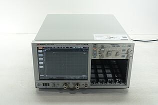
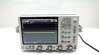
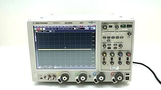
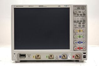
- Get Precision at a Fraction of the Cost – Explore Our Certified Used Equipment
- What is a Low Pass Filter?
- Types of Low Pass Filters
- RC Low Pass Filter
- RL Low Pass Filter
- Inverting Op Amp Low Pass Filter
- Non-Inverting Op Amp Low Pass Filter
- Formulas Used in Low Pass Filter Calculations
- Factors That Can Affect Your Low Pass Filter Calculations
- Component Tolerances
- Environmental Factors
- Load Impedance
- Parasitic Elements
- Aging of Components
- Frequency Range of Operation
- Practical Applications of Low Pass Filters
- How to Design a Low Pass Filter
- Tools Commonly Used in Low Pass Filter Calculations
- Common Mistakes and Troubleshooting
- Enhance Your Circuit Design with Accurate Low Pass Filter Calculations
- Whenever You’re Ready, Here Are 5 Ways We Can Help You

Low Pass Filter

High Pass Filter

Ever tried to design a low pass filter and found yourself buried in conflicting online advice and complex formulas?
Maybe you’ve spent hours juggling formulas, scrolling through endless forums, or testing different values only to find that your circuit still isn’t filtering out the noise like you hoped.
Or perhaps you’ve got a critical project—like designing audio equipment where even a hint of high-frequency interference could ruin the sound—and you’re wondering if there’s an easier way to nail down those perfect component values.
That’s where a Low Pass Filter Calculator comes in. Think of it as your go-to tool for quickly finding the right resistor and capacitor values, cutting out all the guesswork. Instead of drowning in complex calculations or worrying about whether you’ve made a mistake, you just enter a few parameters, click a button, and instantly get the cutoff frequency and time constant you need.
No more wasted time or frustration—just a straightforward way to ensure your filter does exactly what it’s supposed to: eliminate unwanted frequencies without touching the signal you care about. Let’s dive into how you can use this calculator to streamline your filter design and make your next project a success.
How to Use the Low Pass Filter Calculator?
A Low Pass Filter Calculator simplifies the process of designing a filter by providing an easy way to compute the necessary component values to achieve your desired cutoff frequency. It’s a handy tool for engineers who want to save time and avoid the frustration of manual calculations or conflicting information.
Step-by-Step Guide to Using the Calculator:
- Select the filter type: Choose between the "Low Pass" or "High Pass" tab, depending on the type of filter you want to design.
- Enter the resistance value: Input the resistance (in ohms, Ω) for your circuit. This value determines how much the filter will resist the flow of current.
- Enter the capacitance value: Input the capacitance (in farads, F). The capacitor determines how much charge it can store and how quickly it can release that charge, affecting the filter's behavior at different frequencies.
- Click "Calculate": Press the "Calculate" button to see the cutoff frequency and time constant based on the values you've entered.
- Review the results:
- Cutoff frequency (Hz): The frequency at which the filter starts to attenuate the signal. A lower cutoff frequency means more of the higher frequencies will be blocked.
- Time constant (seconds): Indicates how quickly the filter responds to changes in input. A smaller time constant means the filter will react faster to changes.
By following these steps, you can determine the optimal resistor and capacitor values needed to design a low pass filter that meets your specifications. This calculator removes the guesswork from filter design, letting you focus on refining your circuit's performance.
Get Precision at a Fraction of the Cost – Explore Our Certified Used Equipment
What is a Low Pass Filter?
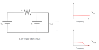
A low pass filter is a fundamental electronic circuit that allows frequencies below a specific threshold to pass through while reducing or blocking frequencies higher than that threshold. Imagine you're listening to music through a speaker— a low pass filter would let the bass notes come through clearly while cutting out any high-pitched noise that you don't want to hear.
Function and Purpose:
The primary purpose of a low pass filter is to clean up a signal by eliminating unwanted high-frequency components, such as noise or interference, while allowing the important low-frequency signals to remain intact. This is particularly useful in audio applications, radio communications, and signal processing, where maintaining signal clarity is crucial.
How Low Pass Filters Work:
At the core of a low pass filter’s operation is the concept of the cutoff frequency. This is the frequency point at which the filter begins to attenuate (reduce the strength of) the higher frequencies. Frequencies below this point pass through the filter with little to no reduction, while frequencies above the cutoff are progressively weakened.
A typical low pass filter consists of a resistor (R) and a capacitor (C) arranged in a series or parallel configuration. Here’s a simplified explanation of how it works:
- Capacitor’s role: In a low pass filter, the capacitor charges and discharges based on the input signal frequency. At high frequencies, the capacitor doesn't have enough time to charge fully, creating a path of lower resistance that bypasses the rest of the circuit—effectively reducing those high frequencies.
- Resistor’s role: The resistor works in tandem with the capacitor to determine the rate at which the capacitor charges and discharges, which directly influences the filter’s response to various frequencies.
Together, the resistor and capacitor establish the filter's cutoff frequency, calculated as:
fc = 1 / (2πRC)
where:
- fc is the cutoff frequency in Hertz (Hz),
- R is the resistance in ohms (Ω),
- C is the capacitance in farads (F).
The cutoff frequency marks the point where the output signal has dropped to about 70.7% of the input signal strength (or -3 dB in terms of power). Beyond this frequency, the attenuation of the signal increases, making the filter highly effective in isolating the desired frequencies from the unwanted noise.
Understanding the basics of how a low pass filter works helps you see why it’s an essential tool for any engineer looking to manage signal integrity and quality in various electronic applications.
Types of Low Pass Filters
There are several types of low pass filters, each suited to specific applications depending on the requirements of the circuit. The table below compares the different types based on construction, operation, advantages, and applications.
| Filter Type | Construction | Operation | Advantages | Applications |
| RC Low Pass Filter | Resistor and Capacitor | Attenuates high frequencies by charging/discharging a capacitor | Simple, low cost, easy to implement | Audio equipment, basic signal processing |
| RL Low Pass Filter | Resistor and Inductor | Attenuates high frequencies using inductive reactance | Handles higher power, better performance in high-current circuits | Power supplies, motor control |
| Inverting Op Amp Low Pass Filter | Operational Amplifier, Resistor, Capacitor | Uses an op-amp to filter signals while inverting the output | Provides gain, better precision, and control over frequency response | Active filter circuits, signal conditioning |
| Non-Inverting Op Amp Low Pass Filter | Operational Amplifier, Resistor, Capacitor | Similar to inverting but maintains the same phase as input | Non-inverted output, high input impedance | Audio processing, buffering, signal amplification |
RC Low Pass Filter
An RC (resistor-capacitor) low pass filter is one of the simplest types of low pass filters. It consists of a resistor and a capacitor connected in series with the input signal. The output is taken across the capacitor.
- Construction and operation: In this filter, the capacitor charges and discharges based on the input signal’s frequency. At lower frequencies, the capacitor has time to charge fully, allowing the signal to pass through with minimal attenuation. At higher frequencies, the capacitor doesn’t have enough time to charge fully, creating a low-resistance path to ground and attenuating the high-frequency components.
- Common usage: RC low pass filters are commonly used in simple circuits where only basic filtering is required, such as audio signal processing or eliminating noise in DC power supplies.
- Example calculation:
To determine the cutoff frequency (fc) of an RC low pass filter:
fc = 1 / (2πRC)
For example, if you have a resistor of 1 kΩ (R = 1000 Ω) and a capacitor of 1 µF (C = 1e-6 F):
fc = 1 / (2 * π * 1000 * 1e-6) ≈ 159.15 Hz
RL Low Pass Filter
An RL (resistor-inductor) low pass filter uses a resistor and an inductor instead of a capacitor to filter out high-frequency signals.
- Construction and operation: In an RL filter, the inductor opposes changes in current. At higher frequencies, the inductor’s reactance increases, creating a higher impedance path, which attenuates the signal. At lower frequencies, the inductive reactance is low, allowing the signal to pass with minimal resistance.
- Advantages and disadvantages: The RL filter is more suitable in applications where inductance is more favorable than capacitance, such as high-power circuits or where energy storage in magnetic fields is desired. However, inductors are bulkier and more expensive than capacitors, making the RL filter less ideal for compact or low-cost applications.
- Example calculation:
To calculate the cutoff frequency (fc) for an RL low pass filter:
fc = R / (2πL)
If R = 1000 Ω and L = 10 mH (L = 0.01 H):
fc = 1000 / (2 * π * 0.01) ≈ 15.92 kHz
Inverting Op Amp Low Pass Filter
An inverting op-amp low pass filter uses an operational amplifier to create more complex filtering circuits with additional benefits, such as gain control.
- Construction and operation: This configuration involves an op-amp with a feedback resistor and a capacitor. The signal is fed into the inverting input, and the non-inverting input is grounded. The op-amp amplifies the input signal while also filtering it, providing an output that is both filtered and inverted.
- Advantages: This type of filter offers better precision and allows for gain control, making it ideal for active filtering applications where both filtering and amplification are needed.
- Example calculation:
To determine the cutoff frequency (fc) and gain (A) for an inverting op-amp low pass filter:
fc = 1 / (2πR2C)
A = -R2 / R1
If R1 = 1 kΩ, R2 = 10 kΩ, and C = 1 µF:
fc = 1 / (2 * π * 10000 * 1e-6) ≈ 15.92 Hz
A = -10000 / 1000 = -10 (The negative sign indicates phase inversion)
Non-Inverting Op Amp Low Pass Filter
A non-inverting op-amp low pass filter uses an operational amplifier but maintains the same phase between the input and output signals.
- Construction and operation: In this configuration, the input signal is applied to the non-inverting input of the op-amp. The filter allows for a non-inverted output, making it suitable for applications requiring a high input impedance and where signal phase preservation is important.
- Comparison with inverting configuration: Compared to the inverting configuration, the non-inverting filter provides a non-inverted output and a high input impedance but may be more complex to design if gain control and precision are critical.
- Example calculation:
To determine the cutoff frequency (fc) and gain (A) for a non-inverting op-amp low pass filter:
fc = 1 / (2πR2C)
A = 1 + (R2 / R1)
If R1 = 1 kΩ, R2 = 10 kΩ, and C = 1 µF:
fc = 1 / (2 * π * 10000 * 1e-6) ≈ 15.92 Hz
A = 1 + (10000 / 1000) = 11
By understanding the different types of low pass filters, you can choose the most suitable option for your specific application, whether it's for basic filtering or more complex signal processing tasks.
Formulas Used in Low Pass Filter Calculations
Low pass filters rely on specific formulas to determine key parameters, such as the cutoff frequency, which defines how the filter separates desired signals from unwanted noise. Understanding these formulas is essential to designing filters that meet your application’s requirements.
Key Formulas for Low Pass Filters
- Cutoff frequency (RC Low Pass Filter):
The cutoff frequency (fc) of an RC low pass filter is calculated using the formula:
fc = 1 / (2πRC)- fc (Cutoff Frequency): The frequency at which the filter begins to significantly attenuate high-frequency signals. Below this frequency, signals pass through the filter with minimal attenuation.
- R (Resistance): The resistance in ohms (Ω) that controls how quickly the capacitor charges and discharges.
- C (Capacitance): The capacitance in farads (F) that determines the filter's ability to store and release electrical energy.
- The resistance (R) and capacitance (C) values interact to set the cutoff frequency. A higher resistance or capacitance will lower the cutoff frequency, allowing fewer high frequencies to pass through.
Example calculation for RC filter:
If R = 1 kΩ (1000 ohms) and C = 0.1 µF (0.1e-6 farads):
fc = 1 / (2 * π * 1000 * 0.1e-6) ≈ 1591.55 Hz
This filter will attenuate frequencies higher than approximately 1591.55 Hz. - Cutoff frequency (RL Low Pass Filter):
For an RL low pass filter, the cutoff frequency (fc) is determined by the formula:
fc = R / (2πL)- fc (Cutoff Frequency): The frequency beyond which the filter starts to attenuate higher frequencies.
- R (Resistance): The resistance in ohms (Ω) that works in conjunction with the inductor to set the cutoff frequency.
- L (Inductance): The inductance in henries (H) that opposes changes in current and affects the filter's response to different frequencies.
- The inductance (L) and resistance (R) determine how the filter responds to changes in current. A higher inductance or lower resistance decreases the cutoff frequency, allowing fewer high frequencies to pass.
Example calculation for RL filter:
If R = 10 Ω and L = 0.05 H (50 mH):
fc = 10 / (2 * π * 0.05) ≈ 31.83 Hz
This filter will start attenuating frequencies above 31.83 Hz. - Cutoff frequency (Inverting op-amp low pass filter):
The cutoff frequency for an inverting op-amp low pass filter is given by:
fc = 1 / (2πR2C)- fc (Cutoff Frequency): The frequency at which the filter begins to attenuate high-frequency signals.
- R2 (Feedback Resistance): The resistance in the feedback loop, which directly affects the cutoff frequency.
- C (Capacitance): The capacitance in the feedback loop that determines the filter's frequency response.
- In this configuration, adjusting R2 or C changes the cutoff frequency, allowing you to control the range of frequencies filtered by the op-amp circuit.
Example calculation for inverting op-amp filter:
If R2 = 10 kΩ (10,000 ohms) and C = 1 µF (1e-6 farads):
fc = 1 / (2 * π * 10,000 * 1e-6) ≈ 15.92 Hz
The filter will begin attenuating frequencies higher than 15.92 Hz. - Cutoff frequency and gain (non-inverting op-amp low pass filter):
The cutoff frequency for a non-inverting op-amp low pass filter is calculated similarly:
fc = 1 / (2πR2C)
The gain (A) for a non-inverting op-amp low pass filter is given by:
A = 1 + (R2 / R1)- fc (Cutoff Frequency): The frequency beyond which the filter begins to attenuate high-frequency signals.
- A (Gain): The ratio of the output voltage to the input voltage, determined by the resistances R1 and R2.
- R1 and R2 (Resistances): The resistances in the circuit that define the filter's gain.
- This configuration allows for gain while maintaining a non-inverted output, which can be beneficial in applications requiring signal amplification without phase inversion.
Example calculation for non-inverting op-amp filter:
If R1 = 2 kΩ (2000 ohms), R2 = 10 kΩ (10,000 ohms), and C = 0.01 µF (0.01e-6 farads):
fc = 1 / (2 * π * 10,000 * 0.01e-6) ≈ 1.59 kHz
A = 1 + (10,000 / 2,000) = 6
This filter will attenuate frequencies above 1.59 kHz and have a gain of 6.
Applying the Formulas in Different Low Pass Filters
Understanding these formulas allows you to design low pass filters tailored to your specific application.
These calculations help fine-tune the cutoff frequency and gain characteristics for optimal performance in audio signal filtering, power supply stabilization, and data signal conditioning.
By adjusting the resistors, capacitors, and inductors, you can optimize the filter to effectively manage the frequencies that matter most for your design.
Factors That Can Affect Your Low Pass Filter Calculations
Several factors can influence the accuracy and effectiveness of your low pass filter calculations. Understanding these factors will help you design filters that perform as expected in real-world applications.
Component Tolerances
Every electronic component, such as resistors, capacitors, and inductors, comes with a tolerance value—typically expressed as a percentage. This tolerance represents the range within which the actual value of the component may vary from its stated value.
For example, a resistor labeled as 1 kΩ with a 5% tolerance could have an actual resistance anywhere between 950 Ω and 1050 Ω. Such variations can shift the cutoff frequency, affecting how well the filter attenuates unwanted frequencies.
Similarly, capacitors and inductors with varying capacitance and inductance values can change the filter's response, making it crucial to select components with tight tolerances for precise filtering.
Environmental Factors
Electronic components are sensitive to temperature changes. For instance, resistance in resistors can increase with temperature due to the thermal coefficient of resistance. Similarly, capacitors and inductors can experience shifts in capacitance and inductance due to temperature variations.
These changes can affect the calculated cutoff frequency, resulting in a filter that behaves differently under varying environmental conditions. Designing filters with components that have low temperature coefficients or compensating for temperature variations in the design phase can help maintain consistent performance.
Load Impedance
The impedance of the load connected to the filter can significantly impact the filter's actual cutoff frequency and response. When designing a filter, it's essential to consider the input and output impedances of the source and the load.
A mismatch between the filter's designed impedance and the actual load impedance can alter the expected performance, shifting the cutoff frequency or changing the filter's attenuation characteristics. To ensure accurate results, match the filter’s impedance with the load it drives or include buffer stages to isolate the filter from variations in load impedance.
Parasitic Elements
Parasitic resistance, inductance, and capacitance exist in all real-world components and circuit layouts. These parasitic elements can introduce unwanted frequency-dependent behavior that affects the filter’s performance.
For example, PCB traces have inherent inductance and resistance, while capacitors may have a small series resistance (ESR) and inductors a small series resistance (DC resistance). These parasitics can create unintended effects, such as additional phase shifts or gain variations, altering the filter’s actual response.
Aging of Components
Over time, electronic components can change their values due to aging effects. Capacitors may lose capacitance, resistors may increase in resistance, and inductors may change their inductance.
These changes can cause the filter’s performance to drift, making it essential to consider component lifespan and degradation when designing filters, particularly for long-term applications.
Frequency Range of Operation
The performance of some components, such as capacitors and inductors, can vary across different frequency ranges. For instance, certain capacitors may exhibit different capacitance values or losses at high frequencies due to dielectric absorption or equivalent series resistance (ESR).
When designing a low pass filter, consider the operational frequency range and select components rated for stable performance within that range.
By accounting for these factors in your low pass filter design, you can ensure a more accurate and reliable filter that performs as expected under various conditions. This approach helps minimize the impact of tolerances, environmental changes, and other influences on your filter's performance, resulting in a design that effectively meets your application's requirements.
Practical Applications of Low Pass Filters
Low pass filters play a critical role in a wide range of applications across various fields. Here are some of the practical uses:
- Audio Engineering
- Smooth out audio signals by removing high-frequency noise or hiss.
- Separate different audio frequency bands (bass, mid, treble) in crossover networks for speaker systems.
- Implement anti-aliasing filters in digital audio conversion to prevent unwanted frequencies from causing distortion during sampling.
- Signal Processing
- Filter out high-frequency noise from analog signals before converting them to digital formats.
- Enhance the quality of signals by reducing unwanted components in instrumentation and measurement systems.
- Use in data smoothing and removing rapid changes or spikes from data signals in control systems.
- RF Communications
- Limit the bandwidth of transmitted signals to comply with regulatory standards.
- Reduce out-of-band noise in receivers to improve signal-to-noise ratio.
- Filter out high-frequency interference from power supplies or other components in radio frequency circuits.
- Power Supplies
- Filter out ripple voltage and noise in DC power supplies to provide a stable output voltage.
- Prevent high-frequency noise from switching regulators from affecting sensitive electronic circuits.
- Image Processing
- Reduce high-frequency noise in digital images to create smoother and clearer images.
- Implement in hardware such as cameras and scanners to improve image quality by filtering unwanted noise.
- Biomedical Devices
- Remove high-frequency noise from biological signals like ECG and EEG to ensure accurate diagnosis.
- Filter out muscle noise in EMG signals to focus on relevant frequencies.
How to Design a Low Pass Filter
Designing a low pass filter involves selecting the appropriate components and configurations to achieve the desired performance. Follow these steps to design a low pass filter from scratch.
- Determine the desired cutoff frequency
- Decide the cutoff frequency (fc) that defines the point where the filter starts to attenuate high-frequency signals. This frequency depends on your application's requirements, such as the frequency range you need to preserve or eliminate.
- Choose the filter type
- Select the type of low pass filter (e.g., RC, RL, or Op-Amp-based) based on the application's complexity, performance, and cost considerations. RC filters are simpler and cost-effective for low-frequency applications, while RL and Op-Amp filters may be preferred for high-power or precision filtering.
- Select the right components
- Choose resistors, capacitors, and inductors that match the desired cutoff frequency and filter type:
- For an RC filter, calculate the values of R and C using the formula:
fc = 1 / (2πRC) - For an RL filter, calculate the values of R and L using the formula:
fc = R / (2πL) - For an Op-Amp filter, select appropriate resistors and capacitors based on the configuration (inverting or non-inverting) and desired gain.
- For an RC filter, calculate the values of R and C using the formula:
- Choose resistors, capacitors, and inductors that match the desired cutoff frequency and filter type:
- Determine the filter order
- Decide on the order of the filter (first-order, second-order, etc.) based on the sharpness of the cutoff and complexity requirements:
- First-order filters: Provide a slope of -20 dB/decade. Suitable for applications where a gentle roll-off is acceptable.
- Second-Order Filters and Higher: Provide steeper roll-offs (-40 dB/decade or more) and better attenuation of unwanted frequencies. Suitable for more demanding applications requiring higher performance.
- Decide on the order of the filter (first-order, second-order, etc.) based on the sharpness of the cutoff and complexity requirements:
- Select the appropriate configuration:
- Choose the filter topology (Butterworth, Chebyshev, Bessel) based on the desired frequency response characteristics:
- Butterworth filters: Provide a maximally flat response in the passband, ideal for applications where a smooth response is critical.
- Chebyshev filters: Provide a sharper cutoff with some ripple in the passband, suitable for applications where steep attenuation is needed.
- Bessel filters: Maintain linear phase response, ideal for applications like audio and data transmission where phase accuracy is crucial.
- Choose the filter topology (Butterworth, Chebyshev, Bessel) based on the desired frequency response characteristics:
- Calculate the component values
- Use the cutoff frequency formula and chosen configuration to calculate the values of the components required to achieve the desired frequency response.
- Prototype and Test:
- Build a prototype of your filter using the selected components and configuration. Test it to ensure it meets the desired performance criteria, and make any necessary adjustments to component values or configuration.
- Refine the design:
- If the filter doesn't meet specifications, adjust the component values, increase the filter order, or change the configuration. Re-test until the filter performs as needed.
Component Selection Table for Low Pass Filters
| Filter Type | Component | Desired Parameter | Typical Value Range | Selection |
| RC Low Pass Filter | Resistor (R) | Cutoff Frequency (fc) | 1 Ω to 1 MΩ | Choose based on fc and practical resistor values. |
| Capacitor (C) | Cutoff Frequency (fc) | 1 pF to 1 µF | Choose a value to achieve the desired fc. | |
| RL Low Pass Filter | Resistor (R) | Cutoff Frequency (fc) | 0.1 Ω to 10 kΩ | Select based on fc and power rating requirements. |
| Inductor (L) | Cutoff Frequency (fc) | 1 µH to 10 mH | Choose inductance to achieve the desired fc; consider size and cost. | |
| Op-Amp Low Pass Filter | Resistors (R1, R2) | Cutoff Frequency (fc), Gain (A) | 1 kΩ to 100 kΩ | Select R1 and R2 based on fc and desired gain. |
| Capacitor (C) | Cutoff Frequency (fc) | 10 pF to 1 µF | Choose capacitance to achieve the desired fc. |
By following these steps and using the component selection table, you can design a low pass filter tailored to your application's needs, ensuring effective filtering and signal quality.
Tools Commonly Used in Low Pass Filter Calculations
Accurate measurement instruments are essential when designing, testing, and fine-tuning low pass filters. The following tools ensure your filter performs as expected.
- Multimeters
- Multimeters measure essential parameters like resistance, capacitance, and voltage, which are crucial for verifying the values of the components used in your filter design.
- Allow you to check for any variations in component values that could affect the filter’s cutoff frequency and overall performance.
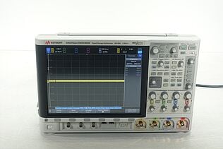
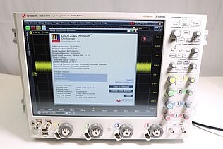
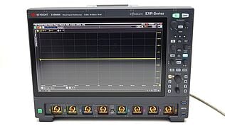
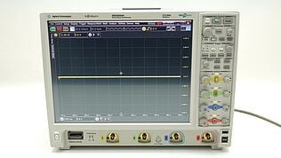
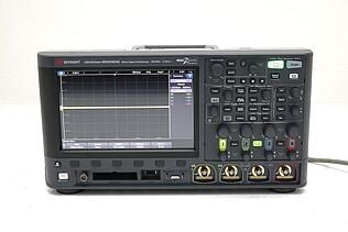
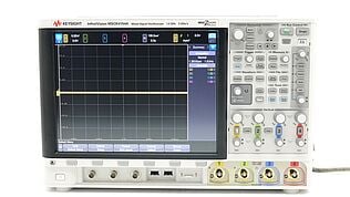
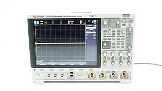
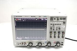
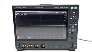
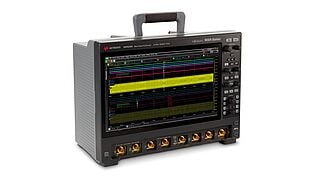
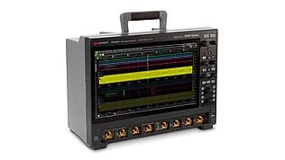
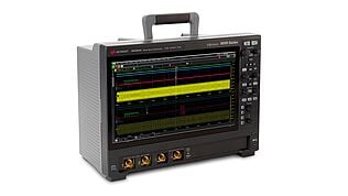
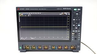
- Oscilloscopes
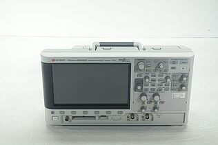
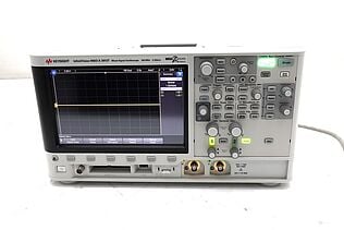
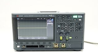
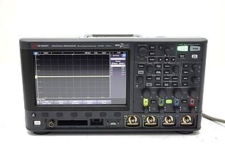
- Oscilloscopes visualize the signal before and after the filter to see how effectively the filter attenuates unwanted high frequencies.
- Measure the filter’s response to different frequencies, helping you adjust the design for the desired cutoff frequency and gain.
- Signal Generators
- Using a signal generator you can generate precise test signals across a range of frequencies to evaluate the filter’s performance.
- Allow you to sweep frequencies to determine the exact point at which the filter starts to attenuate signals, ensuring that the cutoff frequency is as designed.
- LCR Meters
- Measure inductance (L), capacitance (C), and resistance (R) with high accuracy, helping you confirm that your components meet the required specifications.
- Provide more accurate readings than general-purpose multimeters, especially for inductance and capacitance values critical in filter design.
- Network Analyzers
- With a network analyzer you can test the frequency response of the filter across a broad frequency range, providing a detailed picture of how the filter behaves.
- Useful for designing filters that operate at higher frequencies or in more complex circuits, such as RF communication systems.
Importance of Calibration
- Regular calibration of measurement tools ensures that your instruments provide accurate readings, which is crucial for precise filter design.
- Maintains consistency in measurements, reducing the risk of errors due to drift or aging of components within the instruments.
- Verifies that your tools comply with industry standards, enhancing the reliability of your measurements and ultimately your filter design.
Benefits of Buying Premium Used Equipment from Keysight
- Cost Savings
- Used and refurbished equipment from Keysight offers high-quality tools at a lower price, allowing you to access premium test equipment without exceeding your budget.
- Helps stretch your resources, especially when outfitting a new lab or replacing outdated tools.
- Shorter Lead Times
- Keysight's used equipment is often available for immediate shipment, reducing wait times compared to purchasing new instruments, which may have longer lead times.
- Allows you to start testing and fine-tuning your filter designs sooner, speeding up your development process.
- Certified Quality
- All premium used equipment from Keysight undergoes a comprehensive 10 point refurbishment process and calibration to meet the same standards as new equipment, ensuring reliability and accuracy.
- Comes with a warranty and support options, giving you confidence in your purchase and ongoing technical support.
Using accurate, well-calibrated instruments is vital for designing effective low pass filters. Buying refurbished equipment from reputable sources like Keysight can offer both quality and savings, helping you achieve precise results without compromising on performance.
Common Mistakes and Troubleshooting
Designing and using low pass filters can present challenges. Here are some common mistakes and troubleshooting tips to help you avoid issues and achieve optimal filter performance.
- Incorrect component values
- Using resistors, capacitors, or inductors with incorrect values can shift the cutoff frequency and degrade filter performance.
- Troubleshooting: Recheck calculations and component specifications. Verify values with a multimeter or LCR meter to ensure they match design requirements.
- Ignoring parasitic elements
- Overlooking parasitic capacitance, inductance, or resistance in components and PCB traces can alter the filter's frequency response.
- Troubleshooting: Consider parasitics in your design calculations. Use a network analyzer to identify unintended frequency shifts and adjust the layout or components accordingly.
- Poor layout and grounding
- Improper PCB layout or grounding can introduce noise and unwanted interference, affecting filter behavior.
- Troubleshooting: Optimize the layout by minimizing trace lengths and ensuring proper grounding. Use shielded cables and separate analog and digital grounds if possible.
- Mismatched impedances
- Failing to match the filter's impedance with the source or load can cause unexpected attenuation or signal distortion.
- Troubleshooting: Use a buffer stage or impedance-matching network to align the filter’s impedance with connected components.
- Overlooking component tolerances
- Assuming ideal component values without accounting for tolerances can lead to inaccuracies in cutoff frequency.
- Troubleshooting: Select components with tighter tolerances or recalibrate the filter design to accommodate variations.
Diagnosing and Correcting Issues
- Re-evaluate component selection
- Check if the selected components meet the required tolerance and specifications. Replace any components that deviate significantly from expected values.
- Recalculate filter parameters
- Recalculate cutoff frequency, gain, and other parameters to ensure they align with your design goals. Adjust the component values accordingly.
- Adjust design layout
- Modify the PCB layout to reduce parasitic elements or improve grounding. Use simulation tools to analyze the impact of layout changes on filter performance.
Use of Simulation Tools
- Simulate before building
- Use software tools like LTspice to simulate the filter’s performance under various conditions. This allows you to identify and fix potential issues before physical implementation, saving time and resources.
By being mindful of these common mistakes and using a methodical approach to troubleshooting, you can refine your low pass filter designs for optimal performance.
Enhance Your Circuit Design with Accurate Low Pass Filter Calculations
Designing the perfect low pass filter can be challenging—whether it's choosing the right components, managing parasitic elements, or dealing with unexpected performance issues.
But you don’t have to struggle with endless calculations or worry about flawed designs. With the right tools, careful planning, and accurate measurements, you can achieve reliable results every time.
Our premium used equipment, like multimeters, oscilloscopes, and signal generators from Keysight, makes high-quality testing accessible and affordable, ensuring that your filter designs meet their full potential.
Don’t let guesswork hold you back; enhance your circuit designs with precision and confidence. Start designing with accuracy today.
Whenever You’re Ready, Here Are 5 Ways We Can Help You
- Browse our Premium Used Network Analyzers, Oscilloscopes, Signal Analyzers and Waveform Generators
- Call tech support US: 1 800 829-4444 Press #, then 2. Hours: 7 am – 5 pm MT, Mon– Fri
- Talk to our sales support team by clicking the icon (bottom right corner) on every offer page.
- Create an account to get price alerts and access to exclusive waitlists
- Talk to your account manager about your specific needs.

