- Introduction
- What is a Multimeter?
- Selecting the Right Multimeter for Switch Testing
- How Switches Work
- Types of Switches
- Safety Precautions When Testing Switches
- Setting Up Your Multimeter for Switch Testing
- How to Test a Switch's Functionality
- Analyzing the Results
- Troubleshooting Common Switch Issues
- Advanced Testing Methods
- How to Maintain Your Multimeter
- Conclusion: Elevate Your Engineering with Precision Switch Testing Techniques
- Whenever You’re Ready, Here Are 5 Ways We Can Help You
Imagine you're deep into developing a prototype for an advanced drone intended for search and rescue operations. This drone is loaded with high-tech sensors and communication tools, all designed to handle the most challenging environments and send back vital data in real time.
Despite rigorous testing, the results are inconsistent. Initially, you suspect the culprit might be complex software bugs or sensor issues. Yet, the actual problem proves to be much simpler and just as significant: a critical switch that activates the drone's emergency communication fails to work correctly due to a faulty connection.
It's only when you use a quality multimeter to meticulously test the electrical continuity that you pinpoint this seemingly minor but crucial issue. This discovery solves the puzzle and highlights the vital role of a reliable multimeter in ensuring the functionality and reliability of the important projects you work on.
For engineers, becoming proficient in using a multimeter to test switches isn’t just about solving problems—it’s about preventing them. Using this tool is crucial for accurate issue diagnosis, fast and effective solutions, and ensuring system reliability.
This guide will show you how to leverage a multimeter for switch testing, improving your ability to maintain and design robust circuits. Let's uncover how to tackle switch failures head-on, improving your projects' overall success.
What is a Multimeter?
A multimeter is a tool that allows you to measure key electrical characteristics: voltage, current, and resistance. This versatility makes it indispensable for diagnosing electrical issues across a wide range of devices, from simple household appliances to sophisticated electronic circuits.
There are two main types of multimeters: analog and digital.
- Analog multimeters use a needle to display readings across a printed scale. While they have their place in electrical work, interpreting the precise values can sometimes be challenging, especially for those new to electrical diagnostics.
- Digital multimeters (DMMs), however, present readings as numerical values on an LCD screen, offering clear and immediate feedback. This clarity is particularly advantageous for beginners, providing exact measurements at a glance. Beyond ease of use, digital models boast features like auto-ranging, which automatically adjusts to the proper measurement range for your test.
Given these advantages, digital multimeters are the preferred choice for a broad spectrum of electrical tasks, from professional engineering projects to DIY electronics hobbies.
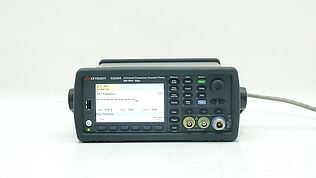
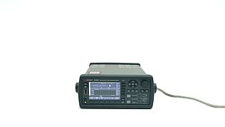
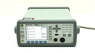
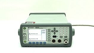
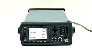
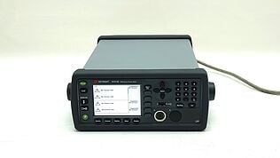
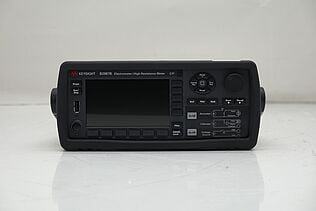
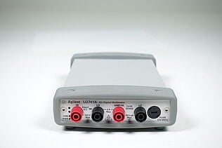
Upgrade Your Toolkit with Keysight's Trusted Refurbished Multimeters
Selecting the Right Multimeter for Switch Testing
Choosing the appropriate multimeter for switch testing is crucial for ensuring accurate and efficient diagnostics. Here are key features to consider:
- Auto-ranging: This feature allows the multimeter to automatically adjust to the correct range for the measurements you're taking, simplifying the testing process and reducing the chance for error, especially useful for quickly determining switch functionality.
- Accuracy: Look for a multimeter with a high degree of accuracy. Precise readings are vital when diagnosing switch issues, as even small discrepancies can lead to misdiagnosis.
- Low resistance measurement capability: The ability to measure low resistance is essential for effective switch testing, as it helps in identifying issues like corrosion or wear in the switch contacts, which can impede performance.
- Durability and reliability: Opt for a multimeter that is known for its durability and reliability. A robust tool can withstand the rigors of regular use and provide consistent, accurate readings over time.
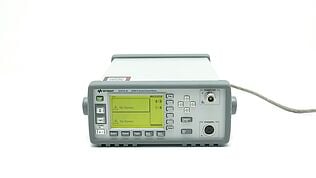
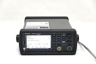
Considering Keysight's premium used multimeters can be a smart move if you are looking for a cost-effective, reliable option. Keysight offers high-quality instruments that are thoroughly tested and recalibrated. Opting for a refurbished model can give you access to high-end features at a fraction of the cost, ensuring you have a dependable tool for your electrical diagnostic needs without breaking the bank.
“All our equipment is Premium Used. I don’t like to call it just “used”, because it’s so much more than used equipment.” – Keysight Account Manager
How Switches Work
At their core, switches are simple yet ingenious devices that control the flow of electricity within a circuit, essentially determining whether an electrical system is active or inactive. They work by either opening (disconnecting) or closing (connecting) electrical pathways, allowing users to turn devices on or off with ease.
When a switch is in the "off" position, it opens the circuit, effectively stopping the flow of electrical current. This disconnection prevents electricity from completing its path, leaving the device without power.
Conversely, flipping the switch to the "on" position closes the circuit, creating a continuous pathway for current to flow. This seamless control over current flow is what allows switches to regulate the operation of virtually any electrical device, from simple household lights to complex industrial machinery.
Understanding the basic mechanism of switches is foundational to grasping how electrical systems function, illustrating how the simple act of opening or closing a circuit can power or power down devices, thereby regulating their operation within an electrical network.
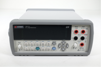
Types of Switches
Switches are essential for managing electrical circuits across a variety of applications, from simple household devices to complex industrial machinery. Here are some common types of switches and their typical uses:
- Single-pole switch: This is the most basic type, used to control a circuit from a single location. It has two terminals and a simple on/off mechanism, making it ideal for controlling lights, fans, and other straightforward devices.
- Double-pole switch: Similar to the single-pole but controls two separate circuits simultaneously. It has four terminals and is used for applications requiring simultaneous operation of two devices or for switching higher voltage appliances.
- Three-way switch: Used in pairs, three-way switches allow you to control a single device from two different locations. This type is often found in stairways, hallways, or any room with two entry points, providing convenient control over lighting.
- Four-way switch: When you need to control a light or device from three or more locations, four-way switches are used in conjunction with two three-way switches. This setup is common in large rooms, multi-story homes, or long hallways, offering flexible control points.
- Toggle switch: A switch that operates by moving a lever back and forth to open or close a circuit. Toggle switches are versatile, used in various settings from industrial machinery to small electronic projects.
- Push button switch: As the name suggests, these switches operate when pressed. They can be momentary, returning to their default state when released, or latching, remaining in their new state until pressed again. Push button switches are common in machinery, devices, and consumer electronics for start/stop functions.
- Rotary switch: This type allows control over a device through a rotating knob with multiple positions, each corresponding to a different circuit connection. Rotary switches are used in applications requiring more than just on and off control, such as selecting different modes of operation.
- Slider switch: Operated by sliding a knob along a track to open or close a circuit, slider switches are often used in lighting dimmers and audio control boards, allowing for gradual adjustments.
Each type of switch offers unique functionalities suited to different applications, highlighting the diversity and versatility of switches in electrical and electronic design.
Safety Precautions When Testing Switches
When testing switches or performing any electrical work, prioritizing safety is paramount. Electricity poses significant risks if not handled with care. Here are essential safety precautions to follow:
- Turn off power at the breaker: Before beginning any tests, ensure the power supply to the circuit you're working on is completely shut off at the breaker. This step is crucial in preventing accidental electrocution or short circuits.
- Verify the absence of voltage: Even after turning off the power, always use a voltage tester to confirm there's no current flowing through the circuit. Never assume a circuit is dead until you have verified it yourself.
- Wear protective gear: Protective eyewear and gloves can shield you from unexpected sparks or exposure to sharp components. Choosing gear rated for electrical work adds an extra layer of safety.
- Use insulated tools: Tools with insulated handles provide added protection against electric shock. Ensure your multimeter and any other equipment you use are in good condition and rated for the voltages you'll be working with.
- Stay informed: Familiarize yourself with the electrical codes and standards relevant to your work. Understanding the principles of electrical safety can help you identify potential hazards before they become serious.
Following these guidelines not only ensures your safety but also protects the integrity of the devices you're working on. When dealing with electricity, always err on the side of caution to prevent accidents and injuries.
Setting Up Your Multimeter for Switch Testing
To effectively test switches with a multimeter, it is essential to correctly set up the device. Here's a detailed guide outlining the step-by-step process to prepare your multimeter for switch testing, with a specific focus on using the continuity test mode:
- Ensure safety: Confirm the power to the circuit is off at the breaker and verify with a voltage tester.
- Select continuity test mode: Turn your multimeter’s dial to the continuity setting, often symbolized by an arrow forming a circle or the sound wave symbol.
- Check multimeter functionality: Before testing the switch, ensure your multimeter is working correctly by touching its probes together. A functioning continuity mode will emit a beep, indicating a complete circuit.
- Prepare the switch for testing: Disconnect the switch from the circuit to isolate it for accurate testing.
- Connect multimeter probes: Attach one probe to one terminal of the switch and the other probe to the other terminal.
The continuity setting on your multimeter is crucial for testing switches because it helps determine if the switch is creating an uninterrupted path for electricity to flow.
When the switch is on (closed), the multimeter should emit a continuous beep, indicating continuity. If there’s no sound, the circuit is open, suggesting a potential issue with the switch.
This method provides a quick and effective way to assess the operational integrity of switches, ensuring they function as intended within electrical systems.
How to Test a Switch's Functionality
Testing a switch's functionality ensures it operates as intended, controlling the flow of electricity through a circuit. Here's how to simulate the switch's operation and interpret multimeter readings for various types of switches:
- Ensure safety: Begin by ensuring all power to the circuit is turned off at the breaker. Use a voltage tester to confirm the absence of live electricity.
- Set your multimeter: For functionality tests, set your multimeter to measure voltage (V) or continuity, depending on the test type you're conducting.
- Prepare the switch: If possible, remove or isolate the switch from its operational environment. This might involve unscrewing the switch from the wall and pulling it out with wires still attached.
Single-Pole Switches
- Continuity check: With the switch in the "off" position, there should be no continuity; in the "on" position, the multimeter should beep, indicating continuity.
- Voltage check: Connect one probe to the terminal connected to the power source and the other to the output terminal. Flip the switch on. A reading close to the source voltage indicates the switch is functional.
Double-Pole Switches
- Perform the same tests as for single-pole switches, but check both sets of terminals individually, as double-pole switches control two separate circuits.
Three-Way Switches
- Continuity check: Test between the common terminal and each traveler terminal separately. As you toggle the switch, continuity should alternate between the traveler terminals.
- Voltage check: With the circuit energized, check for voltage presence at the common terminal when the switch is in different positions, indicating correct operation.
Four-Way Switches
- Continuity check: Test continuity between pairs of diagonally opposite terminals. Toggle the switch; continuity should switch from one pair of diagonal terminals to the other.
Interpreting Multimeter Readings
- Continuity tests: A beep or zero resistance indicates a closed circuit (switch on), while no beep or infinite resistance indicates an open circuit (switch off).
- Voltage tests: A voltage reading close to the expected supply voltage when the switch is "on" indicates proper function. No reading or a significantly lower voltage suggests a malfunction.
By following these steps, you can effectively test the functionality of different types of switches, ensuring they correctly control the electrical flow as designed.
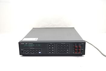
Analyzing the Results
Understanding the results from both continuity and functionality tests is crucial for diagnosing switch health and ensuring electrical system integrity. The outcomes can reveal whether a switch is operating correctly or if it's faulty and requires replacement. Here’s how to interpret the results.
| Test Type | Expected Technical Outcome | Implication |
| Continuity (Switch Off) | Open Circuit (infinite resistance) | Switch is functioning properly by breaking the circuit. |
| Continuity (Switch On) | Closed Circuit (0 Ω resistance) | Switch is functioning properly by closingthe circuit. |
| Voltage (Switch Off) | 0 V or nominal voltage presence | Switch effectively isolates the circuit, preventing current flow. |
| Voltage (Switch On) | Voltage ≈ Source Voltage | Switch is operational, correctly conducting electricity through the circuit. |
Interpreting Results
- Continuity test: In the "off" position, an open circuit (indicated by infinite resistance or no beep) confirms the switch’s ability to break the circuit. A closed circuit (0 Ω resistance or audible beep) in the "on" position shows the switch can complete a circuit, allowing current flow.
- Functionality test: With the switch "off," an absence of voltage or a minimal reading signifies proper isolation of the circuit. A voltage reading nearly equivalent to the source voltage with the switch "on" indicates the switch is correctly facilitating electricity flow.
Implications of Test Outcomes
- Both tests passed: Indicates the switch is fully functional, accurately controlling the electrical flow as designed. This outcome is ideal, confirming system integrity.
- Any test failed: Suggests a malfunction within the switch, which may hinder proper circuit operation. Such a fault requires immediate attention, potentially involving repair or replacement of the switch to ensure system safety and functionality.
This technical analysis assists in pinpointing operational switches and identifying those that may compromise circuit efficiency or safety, providing a clear path for maintenance or troubleshooting.
Troubleshooting Common Switch Issues
Switch testing can sometimes yield inconsistent readings or unexpected results, indicating potential issues. Understanding these common problems and knowing how to address them can save time and ensure electrical systems function correctly. Below is a table that outlines frequent switch issues encountered during testing, along with proposed solutions or next steps.
| Common Issue | Potential Solution |
| Inconsistent Continuity Readings | This may be due to dirty or corroded contacts within the switch. Cleaning the contacts with a contact cleaner and ensuring they are dry can often resolve this issue. |
| No Continuity in "On" Position | A lack of continuity when the switch is supposed to be closed could indicate a broken internal mechanism. Inspect the switch for physical damage; if present, replace the switch. |
| Unexpected Voltage Readings | Unusual voltage levels might result from loose wiring or a bad connection. Tighten all connections and ensure wiring is properly seated in the switch terminals. |
| Switch Feels Loose or Unstable | A switch that wobbles or doesn't stay firmly in position could have loose mounting screws or a deteriorated frame. Tighten screws or replace the switch if the frame is compromised. |
| Arcing or Sparking from Switch | Arcing can occur due to a high current load or a malfunctioning switch. Reduce the load on the circuit if overloaded and consider replacing the switch if the issue persists. |
| Continuity When Switch is "Off" | This could indicate that the switch is always in a closed state, possibly due to an internal short. The switch should be replaced to prevent potential safety hazards. |
Addressing these common issues effectively requires a systematic approach to diagnose and fix the underlying problem. Regular maintenance, such as cleaning contacts and ensuring connections are tight, can prevent many issues. However, some problems may necessitate replacing the switch to ensure the safety and reliability of the electrical system.
Advanced Testing Methods
For diagnosing complex switch issues, beyond the basic continuity and functionality tests, there are advanced techniques that provide deeper insights into the performance and integrity of switches. Two such methods are measuring voltage drop across a switch and dynamic load testing.
Measuring Voltage Drop Across a Switch
This method involves using a multimeter to detect any potential difference between the input and output terminals of a switch when it's in the "on" position. It's particularly useful for identifying issues that don't entirely prevent current flow but create resistance that impedes circuit efficiency.
A healthy switch should show a minimal voltage drop, indicating low internal resistance. A higher reading suggests internal issues, such as corrosion or wear, which might not disrupt continuity but degrade performance.
Dynamic Load Testing
Dynamic load testing involves applying an actual or simulated load to the circuit controlled by the switch, mimicking real-world operating conditions.
This technique is invaluable when switches seem to operate correctly under no-load tests but fail or underperform with a connected load. It can reveal problems like contacts that don't close fully under load or switches that overheat, potentially leading to failure over time.
When to Employ Advanced Methods
These advanced techniques should be considered when initial testing suggests a switch is functional, yet the system it controls still exhibits issues. They are also useful for periodic maintenance checks in critical systems, ensuring switches can handle their intended loads without degradation or failure.
Both voltage drop measurements and dynamic load testing offer insights into the switch's ability to conduct electricity efficiently and perform reliably under actual operating conditions. Employing these methods can help identify and rectify subtle problems, ensuring the longevity and reliability of electrical systems.
How to Maintain Your Multimeter
To ensure your multimeter remains accurate and serves you well over the years, regular care and maintenance are essential. Follow these tips to keep your device in top condition.
- Regular calibration: Schedule regular calibration checks to ensure your multimeter provides accurate readings. Manufacturers often recommend annual calibration, especially for professional use where precision is critical.
- Proper storage: Keep your multimeter in a protective case when not in use to shield it from dust, moisture, and physical damage. Store it in a cool, dry place away from direct sunlight and extreme temperatures.
- Battery maintenance: Replace batteries regularly to prevent leakage that can damage the multimeter's internal components. Check the battery compartment periodically for signs of corrosion.
- Clean gently: Use a soft, dry cloth to clean the exterior of your multimeter. For tougher grime, a cloth slightly dampened with water or mild detergent can be used. Avoid harsh chemicals that can damage the screen or casing.
- Check leads and probes: Inspect the leads and probes for wear or damage before and after use. Replace damaged or frayed leads immediately, as they can lead to inaccurate readings or pose a safety risk.
- Avoid overload: Be mindful of the multimeter's voltage and current ratings. Exceeding these limits can permanently damage the device or compromise its accuracy.
Following these guidelines can significantly extend the life of your multimeter, ensuring it remains a reliable tool for your electrical measurements and diagnostics.
For Keysight multimeters, enhance your peace of mind with KeysightCare. Offering up to 5 years of warranty, this service ensures your equipment remains in peak condition, combining maintenance ease with the assurance of long-term reliability and accuracy. Learn more about how Keysight can support your needs by visiting KeysightCare.

Keep Your Projects on Track with Keysight's Calibration Services
Select up to 3 instruments to compare
Enable Notifications
In order to use this feature, you need to enable notifications.
Manage notification preferences
Conclusion: Elevate Your Engineering with Precision Switch Testing Techniques
This guide has outlined the critical importance of mastering switch testing, a fundamental component of electrical engineering. We've navigated through understanding different switch types, selecting and using a multimeter correctly, applying advanced testing methods, and addressing common switch issues.
Emphasizing safety, accurate measurements, and regular maintenance of your testing equipment is crucial for effective electrical troubleshooting. These practices not only ensure the reliability and safety of your electrical projects but also prevent potential hazards.
Armed with this knowledge, you are now better equipped to integrate these testing techniques into your engineering projects. The field of electrical engineering is vast, constantly evolving, and full of opportunities for innovation and learning.
Paying close attention to details, such as the functionality of switches, distinguishes exceptional engineering work. Precision in switch testing not only solves problems but also enhances the reliability and efficiency of electrical systems.
Let this guide be a stepping stone towards achieving engineering excellence, inspiring you to continuously expand your skills and contribute to the advancement of electrical engineering.
Whenever You’re Ready, Here Are 5 Ways We Can Help You
- Browse our premium used network analyzers, oscilloscopes, signal analyzers and waveform generators.
- Call tech support US: +1 800 829-4444
Press #, then 2. Hours: 7 am – 5 pm MT, Mon– Fri - Talk to our sales support team by clicking the icon (bottom right corner) on every offer page
- Create an account to get price alerts and access to exclusive waitlists.
- Talk to your account manager about your specific needs.

